Request a call back

Join NOW to get access to exclusive study material for best results

Electromagnetic Induction and Alternating Currents

Electromagnetic Induction and Alternating Currents PDF Notes, Important Questions and Synopsis

SYNOPSIS

Magnetic flux
Magnetic flux through a plane of area dA placed in a uniform magnetic field B

begin mathsize 12px style straight ϕ equals integral straight B with rightwards arrow on top. straight d straight A with rightwards arrow on top end style
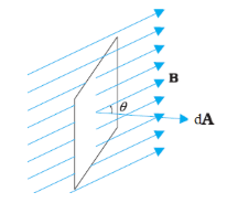
If the surface is closed, then

begin mathsize 12px style straight ϕ equals contour integral straight B with rightwards arrow on top. text    end text straight d with rightwards arrow on top. text   end text straight A equals 0 end style
This is because magnetic lines of force are closed lines and free magnetic poles do not exist.

Electromagnetic Induction: Faraday’s Law

  1. First law: Whenever there is a change in the magnetic flux linked with a circuit with time, an induced emf is produced in the circuit which lasts as long as the change in the magnetic flux continues.

  2. Second law: The induced emf is equal to negative of the rate of change of flux through the circuit.
    Induced emf, begin mathsize 12px style straight E equals negative open parentheses dϕ over dt close parentheses end style

Lenz’s Law
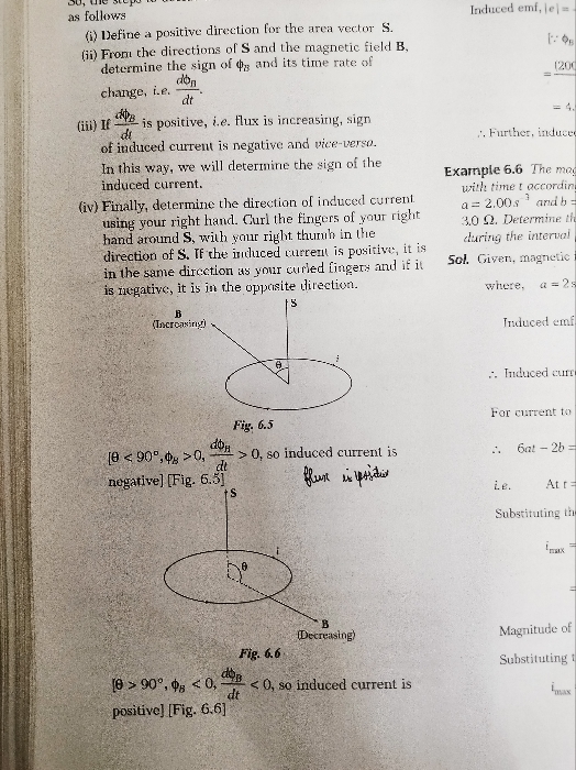
The direction of the induced emf or current in the circuit is such that it opposes the cause by which it is produced, so that

begin mathsize 12px style straight E equals negative straight N open parentheses dϕ over dt close parentheses end style
N → Number of turns in the coil

Lenz’s law is based on energy conservation
Fleming’s right-hand rule: It states that if the thumb and the first two fingers of the right hand are stretched mutually perpendicular to each other and if the forefinger gives the direction of the magnetic field and the thumb gives the direction of motion of the conductor, then the central finger gives the direction of the induced current.

Emf, current and charge induced in the circuit 

  1. Induced emf   
    begin mathsize 12px style straight E equals negative straight N dϕ over dt end style
    begin mathsize 12px style text    end text equals negative fraction numerator straight N open parentheses straight ϕ subscript 2 minus straight ϕ subscript 1 close parentheses over denominator straight t end fraction end style
  2. Induced current
     begin mathsize 12px style straight I equals straight E over straight R equals negative straight N over straight R open parentheses dϕ over dt close parentheses end style
    begin mathsize 12px style equals negative straight N over straight R fraction numerator open parentheses straight ϕ subscript 2 minus straight ϕ subscript 1 close parentheses over denominator straight t end fraction end style

Charge depends only on net change in flux and does not depend on time.

Emf induced due to linear motion of a conducting rod in a uniform magnetic field

begin mathsize 12px style straight E equals negative straight thin space calligraphic l with rightwards arrow on top straight thin space. straight thin space open parentheses straight v with rightwards arrow on top cross times straight B with rightwards arrow on top close parentheses end style

If begin mathsize 12px style straight e with rightwards arrow on top comma straight thin space straight v with rightwards arrow on top    and    straight B with rightwards arrow on top    end style  are perpendicular to each other, then

begin mathsize 12px style straight E equals Bv calligraphic l    end style

Induced emf due to rotation of a conducting rod in a uniform magnetic field 

begin mathsize 12px style straight E equals 1 half text    end text Bω calligraphic l squared equals Bπn calligraphic l squared equals BAn end style

where n is the frequency of rotation of the conducting rod.

Direction of emf is given by the right-hand thumb rule.

Induced emf due to rotation of a metallic disc in a uniform magnetic field 

begin mathsize 12px style straight E subscript OA equals 1 half BωR squared equals BπR squared straight n equals BAn end style

Induced emf, current and energy conservation in a rectangular loop moving in a non-uniform magnetic field with a constant velocity

  1. Net increase in flux crossing through the coil in time Δt
     begin mathsize 12px style Δϕ equals open parentheses straight B subscript 2 minus straight B subscript 1 close parentheses calligraphic l straight v text    end text Δt end style
  2. Emf induced in the coil

  3. If the resistance of the coil is R, then the current induced in the coil is
    begin mathsize 12px style straight I equals straight E over straight R equals fraction numerator open parentheses straight B subscript 1 minus straight B subscript 2 close parentheses over denominator straight R end fraction calligraphic l text   end text straight v end style
  4. Resultant force acting on the coil
    begin mathsize 12px style straight F equals straight I straight thin space calligraphic l open parentheses straight B subscript 1 minus straight B subscript 2 close parentheses    open parentheses towards    left close parentheses end style
  5. Work done against the resultant force
    begin mathsize 12px style straight W equals open parentheses straight B subscript 1 minus straight B subscript 2 close parentheses squared fraction numerator calligraphic l squared straight v squared over denominator straight R end fraction Δt text    end text joule end style
    Energy supplied in this process appears in the form of heat energy in the circuit.
  6. Energy supplied due to flow of current I in time Δt
    H = I²R Δt
    Or begin mathsize 12px style straight H equals open parentheses straight B subscript 1 minus straight B subscript 2 close parentheses squared fraction numerator calligraphic l to the power of 2 text   end text end exponent straight v squared over denominator straight R end fraction Δt text    end text joule end style
    Or H = W

Rotation of a rectangular coil in a uniform magnetic field

  1. Magnetic flux linked with the coil
    begin mathsize 12px style table attributes columnalign left end attributes row cell straight ϕ equals BAN text    end text cosθ end cell row cell text      end text equals BAN text    end text cosωt end cell end table end style
  2. Emf induced in the coil
    begin mathsize 12px style straight E equals dϕ over dt equals BA text    end text Nω text    end text sinωt equals straight E subscript 0 text    end text sinωt end style
  3. Current induced in the coil
    begin mathsize 12px style table attributes columnalign left end attributes row cell straight I equals straight E over straight R equals fraction numerator BAN text   end text straight omega over denominator straight R end fraction text    end text sinωt end cell row cell text    end text equals straight E subscript 0 over straight R text   end text sinωt end cell end table end style
  4. Both emf and current induced in the coil are alternating. 

Self-induction and self-inductance (L)
When an induced emf is produced in the coil on changing the current in a coil, the phenomenon is called self-induction.

  1. begin mathsize 12px style straight ϕ proportional to straight I text    end text or text    end text straight ϕ equals LI end style
    or begin mathsize 12px style straight L equals straight ϕ over straight I end style
  2. begin mathsize 12px style straight E equals negative straight thin space straight L straight thin space dI over dt end style
    where L is a constant called self-inductance or coefficient of self-induction.
    or begin mathsize 12px style straight L equals fraction numerator straight E over denominator negative open parentheses dI divided by dt close parentheses end fraction end style
  3. Self-inductance of a circular coil
    begin mathsize 12px style straight L equals fraction numerator µ subscript 0 straight N squared πR over denominator 2 end fraction equals fraction numerator µ subscript 0 straight N squared straight A over denominator 2 straight R end fraction end style
  4. Self-inductance of a solenoid
    begin mathsize 12px style straight L equals fraction numerator µ subscript 0 straight N squared straight A over denominator calligraphic l end fraction end style
  5. Two coils of self-inductances L1 and L2 placed far away (i.e. without coupling) from each other.
    1. For a series combination:
      L = L1 + L… L

    2. For a parallel combination:
      begin mathsize 12px style 1 over straight L equals 1 over straight L subscript 1 plus 1 over straight L subscript 2 text    end text. ... 1 over straight L subscript straight n end style

Mutual induction and mutual inductance

  1. On changing the current in one coil, if the magnetic flux linked with a second coil changes and an induced emf is produced in that coil, then this phenomenon is called mutual induction.

  2. begin mathsize 12px style straight ϕ subscript 2 proportional to straight I subscript 1 text    end text or text    end text straight ϕ subscript 2 equals MI subscript 1 end style
    Or begin mathsize 12px style straight M equals straight ϕ subscript 2 over straight I subscript 1 end style
  3. begin mathsize 12px style straight E subscript 2 equals negative dϕ subscript 2 over dt equals negative straight M dI subscript 1 over dt end style
    Or begin mathsize 12px style straight M equals fraction numerator straight E subscript 2 over denominator negative open parentheses dI subscript 1 divided by dt close parentheses end fraction end style
  4. M12 = M21 = M

  5. Mutual inductance of two coaxial solenoids
    begin mathsize 12px style straight M equals fraction numerator µ subscript 0 straight N subscript 1 straight N subscript 2 straight A over denominator calligraphic l end fraction end style
  6. If two coils of self-inductance L1 and L2 are wound over each other, then the mutual inductance is given by
    begin mathsize 12px style straight M equals straight K square root of straight L subscript 1 straight L subscript 2 end root end style
    Where K is called the coupling constant.
  7. For two coils wound in the same direction and connected in series,
    L = L1 + L2 + 2M

For two coils wound in the opposite direction and connected in series,
L = L1 + L2 – 2M
For two coils in parallel,
begin mathsize 12px style straight L equals fraction numerator straight L subscript 1 straight L subscript 2 minus straight M squared over denominator straight L subscript 1 plus straight L subscript 2 plus-or-minus 2 straight M end fraction end style

Energy stored in an inductor
Energy stored in the form of Magnetic Field

begin mathsize 12px style straight U subscript straight B equals 1 half straight L text   end text straight I squared subscript max end style

Magnetic energy density

begin mathsize 12px style straight u subscript straight B equals fraction numerator straight B squared over denominator 2 µ subscript 0 end fraction end style

Growth of current in series LR circuit
If a circuit consists of a cell, an inductor L, a resistor R and a switch S connected in series, and the switch is closed at t = 0, the current in the circuit I will increase as
 begin mathsize 12px style straight I equals straight epsilon over straight R open parentheses 1 minus straight e to the power of fraction numerator negative Rt over denominator straight L end fraction end exponent close parentheses end style

The quantity L/R is called the time constant of the circuit and is denoted by τ. The variation of current with time is as shown.

  1. Final current in the circuit=begin mathsize 12px style straight I equals straight epsilon over straight R end style, which is independent of L.
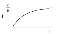
  2. After one time constant, current in the circuit is 63% of the maximum value of current.
    Decay of current in the circuit containing resistor and inductor:
    Let the initial current in a circuit containing inductor and resistor be I0.
    Current at time t is given as begin mathsize 12px style straight I equals straight I subscript 0 straight e to the power of fraction numerator negative Rt over denominator straight L end fraction end exponent end style
    Current after one time constant: I = I0e-1 = 0.37% of initial current
    The time constant τ is defined as the time interval during which the current decays to 37% of the
    maximum current during decay. The rate of decay of the current shows an exponential decay behaviour.

    Eddy current
    When a conductor is moved in a magnetic field, induced currents are generated in the whole volume of the conductor. These currents are called eddy currents.

    Oscillating LC circuit
    If a charged capacitor C is short circuited through an inductor L, the charge and current in the circuit start oscillating simple harmonically. If the resistance of the circuit is zero, no energy is dissipated as heat. We also assume an idealised situation in which energy is not radiated away from the circuit. With these idealisations—zero resistance and no radiation—the oscillations in the circuit persist indefinitely and the energy is transferred from the capacitor’s electric field to the inductor’s magnetic field and back.
    The total energy associated with the circuit is constant. This is analogous to the transfer of energy in man oscillating mechanical system from potential energy to kinetic energy and back, with constant total energy. Charge in the circuit oscillates simple harmonically with angular frequency
     begin mathsize 12px style straight omega equals fraction numerator straight 1 over denominator square root of LC end fraction end style  
    Transformer
    1. It is a device which changes the magnitude of alternating voltage or current.

    2. begin mathsize 12px style straight E subscript straight s over straight E subscript straight p equals straight n subscript straight s over straight n subscript straight p equals straight K end style

    3. begin mathsize 12px style straight I subscript straight p over straight I subscript straight s equals straight n subscript straight s over straight n subscript straight p end style (for ideal transformer)

    4. In an ideal transformer:
      EpIp = EsIs or Pin = Pout 


    5. In a step-up transformer:
      ns > np  or K > 1
       Es > Ep and Is < Ip 


    6. In a step-down transformer:
      ns < np or K < 1
      Es < Ep and Is > Ip 

    7. Efficiency begin mathsize 12px style straight eta equals straight P subscript out over straight P subscript in cross times 100 straight percent sign end style  

Generator or dynamo
It is a device by which mechanical energy is converted to electrical energy. It is based on the principle of EMI.

AC Generator
In an AC generator, mechanical energy is converted to electrical energy by virtue of electromagnetic induction. It consists of a field magnet, armature, slip rings and brushes. If the coil of N turns and area A is rotated at begin mathsize 12px style straight nu end style revolution per second in a uniform magnetic field B, then the motional emf produced is Error converting from MathML to accessible text., where we have assumed that at time t = 0 s, the coil is perpendicular to the field.

Alternating current (AC)
The current whose magnitude changes with time and direction reverses periodically is called alternating current.

  1. Alternating emf E and current I at any time are given by
    begin mathsize 12px style straight E equals straight E subscript 0 text   end text sinωt comma end style where E0 = NBA ω 
    and I = I0 sin (ωt − ϕ); here, I0 = NBA ω/R
    begin mathsize 12px style straight omega equals 2 πn equals fraction numerator 2 straight pi over denominator straight T end fraction straight thin space end style,T → Time period

 Values of alternating current and voltage 

  1. Instantaneous value: It is the value of alternating current and voltage at an instant t.
  2. Peak value: Maximum values of voltage E0 and current I0 in a cycle are called peak values.
  3. Mean value: For a complete cycle,
    < E > = begin mathsize 12px style 1 over straight T integral from 0 to straight T of straight E text   end text dt equals 0 end style
    < I > =begin mathsize 12px style 1 over straight T integral subscript 0 superscript straight T straight I text   end text dt equals 0 end style
    Mean value for a half cycle: Emean= begin mathsize 12px style fraction numerator 2 straight E subscript 0 over denominator straight pi end fraction end style
  4. Root mean square (rms) value:
    Erms = (< E2 >)½ = Error converting from MathML to accessible text.
    and Irms (< I2 >)½ = Error converting from MathML to accessible text.
    RMS values are also called apparent or effective values.

Phase difference between emf (Voltage) and current in an AC circuit

  1. For pure resistance: Voltage and current are in the same phase, i.e. phase difference = 0.
  2. For pure inductance: Voltage is ahead of current by π/2, i.e. phase difference = +π/2.
  3. For pure capacitance: Voltage lags behind current by π/2, i.e. phase difference = −π/2.

Reactance

  1. Reactance begin mathsize 12px style straight X text end text equals straight E over straight I equals straight E subscript 0 over straight I subscript 0 equals straight E subscript rms over straight I subscript rms plus-or-minus straight pi divided by 2 end style
  2. Inductive reactance
    XL =ωL = 2πnL

  3. Capacitive reactance
    begin mathsize 12px style straight X subscript straight C equals 1 over ωC equals fraction numerator 1 over denominator 2 πnC end fraction end style

Impedance

  1. Impedance Z = begin mathsize 12px style straight E over straight I equals straight E subscript 0 over straight I subscript 0 equals straight E subscript rms over straight I subscript rms straight ϕ end style
    where ϕ is the phase difference of the voltage E relative to the current I.

  2. For L–R series circuit:
    ZRL = begin mathsize 12px style square root of straight R squared plus straight X subscript straight L superscript 2 end root equals square root of straight R squared plus ωL squared end root end style
    and tan ϕ = begin mathsize 12px style open parentheses ωL over straight R close parentheses end style or begin mathsize 12px style straight ϕ equals tan to the power of negative 1 end exponent open parentheses ωL over straight R close parentheses end style
  3. For R–C series circuit:
    ZRC = begin mathsize 12px style square root of straight R squared plus straight X subscript straight c superscript 2 end root equals square root of straight R squared plus open parentheses 1 over ωC close parentheses squared end root end style
    and tanϕ = begin mathsize 12px style 1 over ωCR end style or begin mathsize 12px style straight ϕ equals tan to the power of negative 1 end exponent open parentheses 1 over ωCR close parentheses end style
  4. For L–C–R series circuit:
    ZLCR = begin mathsize 12px style square root of straight R squared plus open parentheses straight X subscript straight L minus straight X subscript straight C close parentheses ² end root end style
    begin mathsize 12px style square root of straight R squared plus open parentheses ωL minus 1 over ωC close parentheses ² end root end style
    and begin mathsize 12px style tanϕ equals fraction numerator open parentheses ωL minus 1 over ωC close parentheses over denominator straight R end fraction end style Or begin mathsize 12px style straight ϕ equals tan to the power of negative 1 end exponent open parentheses fraction numerator ωL minus 1 over ωC over denominator straight R end fraction close parentheses end style

Conductance
The reciprocal of resistance is called conductance.

 ∴ Conductance begin mathsize 12px style straight G equals 1 over straight R mho end style

Power in an AC circuit

  1. Electric power = (current in circuit) × (voltage in circuit)
    P = IE

  2. Instantaneous power:
    Pinst = Einst × Iinst 


  3. Average power:
    Pav = begin mathsize 12px style 1 half straight E subscript 0 straight I subscript 0 cosϕ equals straight E subscript rms straight I subscript rms cosϕ end style

  4. Virtual power (apparent power):
    begin mathsize 12px style equals 1 half straight E subscript 0 straight I subscript 0 equals straight E subscript rms straight I subscript rms end style

Power factor

  1. Power factor
    begin mathsize 12px style cosϕ equals straight P subscript av over straight P subscript straight v equals straight R over straight Z end style
  2. For pure inductance:
    Power factor, begin mathsize 12px style cosϕ equals 1 end style

  3. For pure inductance:
    Power factor, begin mathsize 12px style cosϕ equals 0 end style

  4. For LCR circuit:
    Power factor,
     begin mathsize 12px style cosϕ equals fraction numerator straight R over denominator square root of straight R squared plus open parentheses ωL minus 1 over ωC close parentheses ² end root end fraction end style
    begin mathsize 12px style straight X equals open parentheses ωL minus 1 over ωC close parentheses end style

Wattless current
The component of current whose contribution to the average power is nil is called wattless current.
RMS value of wattless current:

begin mathsize 12px style table attributes columnalign left end attributes row cell equals fraction numerator straight I subscript 0 over denominator square root of 2 end fraction sinϕ end cell row cell equals straight I subscript rms sinϕ equals fraction numerator straight I subscript 0 over denominator square root of 2 end fraction open parentheses straight X over straight Z close parentheses end cell end table end style 

Choke coil
An inductive coil used for controlling the alternating current whose self-inductance is high and resistance in negligible is called a choke coil. 
The power factor of this coil is given by

begin mathsize 12px style Cosϕ straight equals fraction numerator straight R over denominator square root of straight R to the power of straight 2 plus straight omega to the power of straight 2 straight L to the power of straight 2 end root end fraction equals straight R over ωL straight left parenthesis as space straight R << ωL right parenthesis end style

Now, as we know that begin mathsize 12px style as space straight R << ωL end style , the power factor is small, and hence, the power absorbed will be very small. Also, on account of its large impedance (large inductance), current passing through the
coil is very small. Hence, such a coil is preferred in electrical circuits for the purpose of adjusting the current to any desired value without significant energy waste.

Series resonant circuit

  1. When the inductive reactance (XL) becomes equal to the capacitive reactance (XC) in the circuit, the total impedance becomes purely resistive (Z = R). In this state, the voltage and current are in the same phase (ϕ= 0), the current and power are maximum and the impedance is minimum. This state is called resonance.

  2. At resonance,
     begin mathsize 12px style straight omega subscript straight r straight L equals fraction numerator 1 over denominator straight omega subscript straight r straight C end fraction end style
    Hence, resonant frequency 
    begin mathsize 12px style straight f subscript straight r equals fraction numerator 1 over denominator 2 straight pi square root of LC end fraction end style  
  3. In resonance, the power factor of the circuit is one.

Half-power frequencies
Frequencies f1 and f2 at which the power is half of the maximum power (power at resonance), i.e.

begin mathsize 12px style straight P equals 1 half straight P subscript max end style and begin mathsize 12px style straight I equals fraction numerator straight I subscript max over denominator square root of 2 end fraction end style  are called half-power frequencies.

Bandwidth
The frequency interval between half-power frequencies is called bandwidth.

∴ Bandwidth Δf = f2 – f1 

For a series LCR resonant circuit,

begin mathsize 12px style Δf equals fraction numerator 1 over denominator 2 straight pi end fraction straight R over straight L end style

Quality factor (Q)

begin mathsize 12px style straight Q equals 2 straight pi cross times fraction numerator Maximum text    end text energy text    end text stored over denominator Energy text    end text dissipated text    end text per text    end text cycle end fraction end style 

begin mathsize 12px style equals fraction numerator 2 straight pi over denominator straight T end fraction cross times fraction numerator Maximum text    end text energy text    end text stored over denominator Mean text    end text power text    end text dissipated end fraction end style

Or begin mathsize 12px style straight Q equals fraction numerator straight omega subscript straight r straight L over denominator straight R end fraction equals fraction numerator 1 over denominator straight omega subscript straight r CR end fraction equals fraction numerator straight f subscript straight r over denominator open parentheses straight f subscript 2 minus straight f subscript 1 close parentheses end fraction equals straight f subscript straight r over Δf end style

Download complete content for FREE PDF
NEET - Physics
Asked by raghnibharti | 11 Mar, 2024, 09:11: PM
ANSWERED BY EXPERT ANSWERED BY EXPERT
NEET - Physics
Asked by rathod1234sujal | 15 Nov, 2022, 07:10: PM
ANSWERED BY EXPERT ANSWERED BY EXPERT
NEET - Physics
Asked by ganjiaswini18 | 24 Jun, 2022, 09:08: PM
ANSWERED BY EXPERT ANSWERED BY EXPERT
NEET - Physics
Asked by jhajuhi19 | 18 May, 2021, 08:55: AM
ANSWERED BY EXPERT ANSWERED BY EXPERT
Get Latest Study Material for Academic year 24-25 Click here
×