Optics
Optics PDF Notes, Important Questions and Synopsis
SYNOPSIS
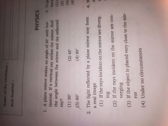
- Laws of reflection: Reflection at a plane surface always occurs in accordance with the following two laws:
- The incident ray, the reflected ray and the normal to the surface at the point of incidence, all lie in the same plane.T
- he angle of incidence i is equal to the angle of reflection r, i.e.∠ i = ∠ r
- Focal length of a spherical mirror:
The distance between the focus and the pole of the mirror is called the focal length of the mirror and is represented by f.
The focal length of a mirror (concave or convex) is equal to half of the radius of curvature of the mirror, i.e. f = R/2.
The straight line joining the pole and the centre of curvature of a spherical mirror extended on both sides is called the principal axis of the mirror.
Note: The focal length of a concave mirror is positive and that of a convex mirror is negative.
- Mirror formula:

where u = distance of the object from the pole of the mirror
v = distance of the image from the pole of the mirror
f = focal length of the mirror - Magnification: Ratio of the size of the image to that of the object.
- Linear magnification m
= ,
where I is the size of the image and O is the size of the object.
When magnification m is positive, the image is real and inverted.
When magnification m is negative, the image is virtual and erect. - Principle of reversibility of light: As light follows a reversible path, we have
 bµa
bµa
Multiplying (i) and (ii), we get
The refractive index of a medium can also be determined from the following: 

where ic is the critical angle.
The critical angle is the angle of incidence in a denser medium corresponding to which the refracted ray just grazes the surface of separation, i.e. the angle of refraction is 90°.
- Apparent depth of a liquid: When the object is placed at the bottom of a transparent medium, say water, and viewed from above, it will appear higher than it actually is.
The refractive index µ in this case is given by the relation:
µ = Real depth/Apparent depth - Refraction through a single surface: If µ1 and µ2 are refractive indices of the first and second media, and R is the radius of curvature of a spherical surface, then we have

Where u and v are the distances of the object and the image, respectively, from the centre of the refracting surface of radius of curvature R. - Refraction through a thin lens: If R1 and R2 are radii of curvature of the first and second refracting surfaces of a thin lens of focal length f, then the lens maker’s formula is

If the lens is surrounded by air, µ 1 = 1 and µ 2 = µ, then
The thin lens formula is
- Magnification produced by a lens:

Where I is the size of the image and O is the size of the object. - Power of a lens: The power of a lens P is its ability to deviate the ray towards the principal axis and is given by

- Refraction through a prism: When a ray of monochromatic light is refracted by a prism, the deviation δ produced by the prism is given by
δ = i + e – A,
Where i = angle of incidence
e = angle of emergence
A = angle of the prism
The angle of deviation δ m is minimum when the ray passes symmetrically through the prism. The refractive index µ of the prism is -
Dispersion: Splitting of white light into its constituent colours is called dispersion.
A prism causes deviation as well as dispersion. -
Optical instruments: Optical instruments are devices which help the human eye in observing highly magnified images of tiny objects, used for detailed examination and in observing objects very far away whether terrestrial or astronomical.
- Human eye: It is the most familiar and complicated optical instrument provided by nature to human beings. In this natural device, light enters through a curved front surface, called cornea, and passes through the pupil, a central hole in the iris. The light is focused by the eye lens on the retina. The retina senses light intensity and colour and transmits the electrical signals via optical nerves to the brain. The brain finally processes the information.
- Microscope: A simple microscope is a convex lens of short focal length. The magnifying power of a simple microscope is

The magnifying power M of a compound microscope is
M = Mo × Me = ,
Where Mo and Me denote the linear magnification of the objective and eye lens.
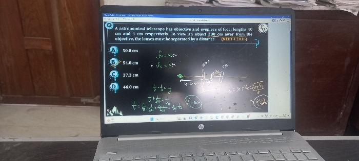
- Telescope:
- Magnifying power M of a refracting telescope is
 and
and
L = (fo − fe), where L = length of the telescope - When the final image is formed at the least distance of distant vision, the magnifying power is given as

- Resolving power of a telescope is

Where λ = wavelength of light
d = diameter of the objective of the telescope
θ = angle subtended by the point object at the objective
- A wavefront is the locus of points with the same phase of oscillation. Rays are lines perpendicular to the wave front which show the direction of propagation of energy. The time taken for light to travel from one wave front to another is the same along any ray.
- Huygens’ principle:
- Each point on the given wavefront (called primary wavefront) acts as a fresh source of new disturbance, called secondary wavelet, which travels in all directions with the velocity of light in the medium.
A surface touching these secondary wavelets tangentially in the forward direction at any instant gives the new wavefront at that instant. This is called the secondary wavefront.
- Huygens’ construction is based on the principle that every point of a wavefront is a source of a secondary wavefront. The envelope of these wavefronts, i.e. the surface tangent to all the secondary wavefronts, gives the new wavefront.
o Doppler effect is the shift in frequency of light when there is a relative motion between the source and the observer. The effect can be used to measure the speed of an approaching or receding object for the source moving away from the observer and for the source moving towards the observer
  . The change in frequency is given as
where we are using the approximation
So,
- Coherent and incoherent addition of waves: Two sources are coherent if they have the same frequency and a stable phase difference. In this case, the total intensity I is not just the sum of individual intensities I1 and I2 due to the two sources but includes an interference term:

where E1 and E2 are the electric fields at a point due to the sources. The interference term averaged over many cycles is zero if the sources have
(a) different frequencies or
(b) the same frequency but no stable phase difference
For such coherent sources,
According to the superposition principle, when two or more wave motions travelling through a medium superimpose one another, a new wave is formed in which the resultant displacement due to the individual waves is the vector sum of displacements produced by each wave at that instant.
The average of the total intensity will be
where ϕ is the inherent phase difference between the two superimposing waves. - Young’s experiment: Two parallel and very close slits S1 and S2 behave like two coherent sources and produce on a screen a pattern of dark and bright bands—interference fringes. For a point P on the screen, the path difference

where d is the separation between two slits, D1 is the distance between the slits and the screen, and y1 is the distance of the point of P from the central fringe.
For constructive interference (bright band), the path difference must be an integer multiple of λ, i.e.
Separation ∆y1 between adjacent bright (or dark) fringes is
using which l can be measured. - Thin film interference:
When the plane wave is incident normally on a thin film of uniform thickness d, the waves reflected from the upper surface interfere with the waves reflected from the lower surface.
Constructive and destructive interference in case of a thin film is given by
- Diffraction refers to light spreading out from narrow holes and slits, and bending around corners and obstacles. The single slit diffraction pattern shows the central maximum (at θ = 0) and zero intensity at angular separation θ = ± (n + ½)λ… (n ¹ 0).
Different parts of the wavefront at the slit act as secondary sources. The diffraction pattern is the result of interference of waves from these sources.
The intensity plot is as follows, with there being a bright central maximum, followed by smaller intensity secondary maxima, with there being points of zero intensity in between, whenever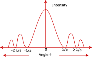
-
Emission, absorption and scattering are three processes by which matter interacts with radiation.
In emission, an accelerated charge radiates and loses energy.
In absorption, the charge gains energy at the expense of the electromagnetic wave.
In scattering, the charge accelerated by incident electromagnetic wave radiates in all directions. - Brewster’s law: When an incident light is incident at the polarising angle, the reflected and refracted rays are perpendicular to each other.
The polarising angle, also called as Brewster’s angle, is given by tanθp = µ
This expression is also called Brewster’s law.
Polarisation specifies the manner in which electric field E oscillates in the plane transverse to the direction of propagation of light. If E oscillates back and forth in a straight line, the wave is said to be linearly polarised. If the direction of E changes irregularly, the wave is unpolarised. When light passes through a single polaroid P1, light intensity is reduced to half, independent of the orientation of P1. - Law of Malus:
If E-vector is at an angle θ with the transmission axis, light is partially transmitted. The intensity of transmitted light is , where I0 is the intensity when the incident E-vector is parallel to the transmission axis.
Polarisation by scattering: Light is scattered when it meets a particle of size similar to its own wavelength. Example: Scattering of sunlight by dust particles. Rayleigh showed that the scattering of light is proportional to the fourth power of the frequency of light or varies as , where λ is the wavelength of light incident on air molecules of size d and d << λ. Hence, blue light is scattered more than red. This explains the blue colour of the sky.
Download complete content for FREE 
NEET - Physics
Asked by kashinathpaikrao89446 | 09 Jul, 2024 10:46: AM
NEET - Physics
Asked by jagadishshnkr | 08 Jul, 2024 08:50: PM
NEET - Physics

Asked by hibasherinichu | 23 Dec, 2023 07:02: AM
NEET - Physics
Asked by myindiaisbad | 06 Jul, 2022 03:36: PM
NEET - Physics
Asked by neetaspirantdoctor | 14 May, 2022 10:59: PM
NEET - Physics
Asked by humerachopda143 | 04 Aug, 2021 08:22: PM
NEET - Physics
Asked by sirib942254 | 15 Jul, 2021 05:32: PM
NEET - Physics
Asked by tasminmazumdar | 01 Jun, 2021 12:48: AM
Related Chapters
- Physics and Measurement
- Kinematics
- Laws of Motion
- Work, Energy and Power
- Rotational Motion
- Gravitation
- Properties of Solids and Liquids
- Thermodynamics
- Kinetic Theory of Gases
- Oscillations and Waves
- Electrostatics
- Current Electricity
- Magnetic Effects of Current and Magnetism
- Electromagnetic Induction and Alternating Currents
- Electromagnetic Waves
- Dual Nature of Matter and Radiation
- Atoms and Nuclei
- Electronic Devices
- Communication Systems