CBSE Class 10 Answered
How can i make a moving coil galvanometer or a dynomo at home ??? PLEASE MENTION STEPS AND DIAGRAMS FOR BOTH
Asked by | 27 May, 2012, 10:01: PM
|
WORKING PRINCIPLE
|
|
| Galvanometer works on the principle of conversion of electrical energy into mechanical energy. When a current flows in a magnetic field it experiences a magnetic torque. If it is free to rotate under a controlling torque, it rotates through an angle proportional to the current flowing through it. | |
|
ESSENTIAL PARTS OF GALVANOMETER
|
|
| There are five essential parts of a Galvanometer. 1. A U-shaped permanent magnet with concave poles. 2. Flat rectangular coil of thin enameled insulated wire C. 3. A soft iron cylinder 'B'. 4. A pointer or needle. 5. A scale. |
|
|
CONSTRUCTION
|
|
|
The flat rectangular coil of thin enameled insulated wire of suitable number of turns wound on a light nonmetallic or aluminum frame is suspended between the cylindrically concave poles of magnet by a thin phosphor bronze strip. One end of the wire of the coil is soldered to strip. The other end of the strip fixed to the frame of the galvanometer and connected to an external terminal. It serves as one leas current lead through which the current enters or leaves the coil. The other end of the wire of the coil is soldered to a loose and soft spiral of wire connected to another external terminal. The soft spiral of a wire serves as the other current lead. A soft-iron cylinder, coaxial with the pole pieces, is placed within the frame of the coil and is fixed to the body of the galvanometer. In the space between it and the pole pieces, where the coil moves freely, the soft iron cylinder makes the magnetic field stronger and radial such that into whatever position the coil rotates, the magnetic field is always parallel to its plane.
 |
|
|
|
|
|
WORKING
|
|
| When a current passes through the galvanometer coil, it experiences a magnetic deflecting torque, which tends to rotate it from its rest position. As the coil rotates it produces a twist in the suspension strip. The twist in the strip produces an electric restoring torque. The coil rotates until the elastic restoring torque due to the strip does not equal and cancels the deflecting magnetic torque, then it attains equilibrium and stops rotating any furthers. | |
Dynamo:
- Acquire the materials you will need. The sizes and specifications can be adjusted to raise the output capacity of your generator, but this is a basic overview of the project.
- 22-28 ga. enameled copper wire. About 500 feet will produce a modest electrical current. More "windings", coupled with a stronger magnet will increase the power output.
- 3 or 4 inch bar magnet. (Should fit lengthwise in the cardboard tube, below, with a little clearance)
- 1/4 inch diameter steel or aluminum rod, 12 inches in length.
- 24 inches of 1X4 lumber.
- 1 - large paper or card board tube, 4-inch diameter.
- 2 - 1/4 inch flat washers.
-
Build a "U" shaped frame to support your "rotor", ie, the permanent bar magnet mounted on a steel shaft. by
- Cut the 1X4 lumber into pieces, 2, at 6 inch lengths, one at 12 inches in length.
- Nail or screw the two 6 inch boards to the 12 inch board at a perpendicular angle to the 12 inch board, which is the base for the rotor frame.
-
Drill two 1/4 inch holes in the two uprights of your frame, aligning them so that the 1/4 inch rod, (the rotor shaft) will go through both without binding.
-
Drill a 1/4 inch hole through the center of your bar magnet, on the flat, or widest side. Be careful to measure the center both in length and width, and drill perpendicularly, so that when the shaft goes through, the magnet will be "square" to the shaft.
-
Slide the metal shaft through one side of the support frame, slide the magnet onto the shaft.
-
Cut a 4 inch section of the paper or cardboard tube. If you don't have a piece of tubing available, you can make one by rolling a sheet of construction paper into a cylinder and gluing or taping it to secure it in this shape. The ideal diameter of the tube will be just large enough to allow the bar magnet to spin freely inside the tube, keeping the magnetic field as near the copper windings as possible.
-
Wind the copper wire around the cardboard or paper tube, leaving about 16 to 18 inches of wire loose on each end to connect to you power test device, an electric light bulb, or other device you will supply power to. The more "turns" or winds around the tube you make, the more power your generator should produce.
-
Slide the tube over the shaft and magnet, then slide the shaft on through the other support frame. You will want several inches of the shaft sticking through each end of the frame.
-
Glue the magnet to the shaft at the center of the two supports, using a high strength hotmelt glue or epoxy. You may choose to drill and tap threads into the magnet for a "set screw" if you have the tools to do so, but the idea is for the magnet to be stationary in relation to the shaft.
-
Support the paper cylinder with the wire windings at the center of the shaft with the bar magnet centered on the wire windings. You may simply cut cardboard legs that can be glued to the cylinder, or build a wire frame from a coat hanger or similar stiff wire to accomplish this.
-
Turn the shaft with your fingers to see if the ends of the magnet hit the inside of the tube. It must turn freely, but be as close as possible to the tube. Again, having the magnet's ends as close the copper wire windings will increase the "exciting" action of the magnetic fields the magnet produces.
-
Glue a washer on each end of the shaft outside the wood supports.
-
Attach the two wires you have loose at the ends of the windings to a flashlight bulb or other low voltage lamp, or connect the test leads from a voltmeter or multimeter to them.
-
Spin the shaft as fast as possible. You may want to wind a string around the end of the shaft as you would a toy "top", then pull it sharply, or just spin it with your fingers. You should get a small voltage, enough to light a 1.5 volt light bulb by manually spinning the shaft.
Answered by | 28 May, 2012, 06:35: AM
Application Videos
-
Power rating
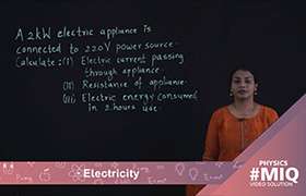 This video shows the calculation of electricity consumed, electric current ...
 -
Some other formulae for calculating power ...
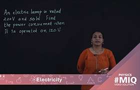 This video shows explains the application of formula for calculating the po...
 -
Cost of electricity
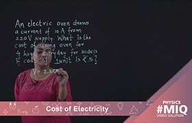 This video describes the calculation of cost of electricity for electrical ...
 -
Combination of resistors -parallel
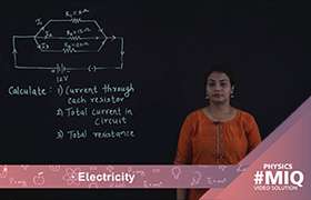 This video describes the calculation of effective resistance, total current...
 -
Combination of resistors -series
 This video describes the calculation of electric current flowing through th...
Concept Videos
-
Electricity
 Define resistance and resistivity, factors on which they depends. Explain ...
 -
Electricity
 Explain Joule's law of heating, heating effect of electric current, electr...
 -
Electricity
 Explain a series and a parallel combination of resistors in a circuit. Det...
 -
Electricity
 Define electric current, direction of current, ampere, potential differenc...
 -
Electricity
 Define resistance and resistivity, factors on which they depends. Explain ...
CBSE 10 - Physics
Asked by khajannirwan | 27 Feb, 2024, 10:20: PM
CBSE 10 - Physics
Asked by saanviyadla | 24 Jan, 2024, 07:06: PM
CBSE 10 - Physics
Asked by kamalaranjanmohantymohanty5 | 06 Jan, 2024, 10:05: AM
CBSE 10 - Physics
Asked by nandhikasugumar | 05 Oct, 2023, 04:01: PM
CBSE 10 - Physics
Asked by daniya062008 | 02 Oct, 2023, 08:25: PM
CBSE 10 - Physics
Asked by prassanna.j | 03 Sep, 2023, 12:28: PM
CBSE 10 - Physics
Asked by prassanna.j | 03 Sep, 2023, 12:21: PM
CBSE 10 - Physics
Asked by prassanna.j | 03 Sep, 2023, 12:13: PM
CBSE 10 - Physics
Asked by prassanna.j | 03 Sep, 2023, 12:11: PM