Class 10 SELINA Solutions Physics Chapter 10 - Electro-magnetism
Electro-magnetism Exercise Ex. 10A
Solution A.1
(c) north-south
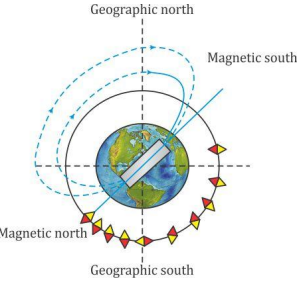
In the presence of earth's magnetic field, a compass needle rests in north-south direction.
Solution A.2
(d) West
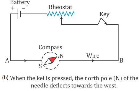
When the key is pressed, a current pass in the wire in the direction from A to B (i.e., from south to north). The north pole of the compass needle will deflect towards the west.
This is because when current flows from South to North it will produce magnetic field along East-West direction, which can be verified using right hand thumb rule. As a result, the magnetic needle align itself in the direction of resultant magnetic field and deflect toward the West.
Solution A.3
(c) both (a) and (b)
In a current carrying conductor, the strength of a magnetic field will depend on:
1. Magnitude of current
2. Direction of current.
Hence the correct option is (c).
Solution A.4
(c) A compass needle
The presence of magnetic field at a point can be detected by a compass needle.
Note: In the presence of a magnetic field, the needle of compass rests only in the direction of magnetic field and in the absence of any magnetic field, the needle of compass can rest in any direction. In the earth's magnetic field alone, the needle rests along north-south direction.
Solution A.5
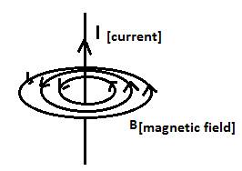
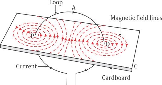
(b) concentric circles
For the given case, when current is passed downward through cardboard, the magnetic field lines form concentric circles, which can be confirmed by sprinkling the iron filling over the cardboard.
Solution A.6
(d) neutral point
Neutral point is a point at which the net magnetic field is zero.
i.e., the point where two magnetic fields are equal but opposite in direction.
Solution A.7
(c) current, magnetic field lines
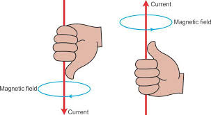
According to right hand thumb rule, if we hold the current carrying conductor in the right hand such that the thumb points in the direction of flow of current, then the fingers encircle the wire in the direction of the magnetic field’s lines.
Solution A.8
(b) anticlockwise, north pole
For the given case, since the current in the wire around the face is in the anticlockwise direction, hence the face has the north polarity.
Solution A.9
(a) The strength of magnetic field due to a bar magnet can be changed.
The strength of the magnetic field due to a bar magnet cannot be changed.
Solution A.10
(c) The polarity of an electromagnet cannot be changed.
The following statements about electromagnets are true:
· It is made of soft iron.
· Its magnetic field strength can be changed.
· The polarity of an electromagnet can be changed by changing the direction of the electric field.
· It can easily be demagnetised.
Hence, the only incorrect option is (c).
Solution A.11
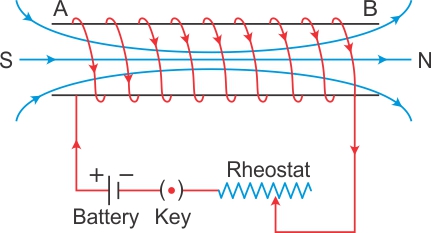
(b) straight and parallel to the axis of solenoid
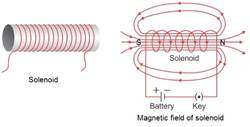
In the inner region of the solenoid, the magnetic field lines become parallel to the axis of the solenoid and remain uniform at any point inside it.
Solution A.12
(a) Gets reversed in direction
By reversing the direction of current in a wire, the magnetic field produced by it gets reversed in direction.
Hint: On reversing the direction of current in a wire, the polarity of the faces of the wire also reverses. Thus, the direction of magnetic field produced by it also gets reversed.
Solution A.13
(b) steel
A strong permanent magnet is made of steel because it has higher magnetic retentivity.
Solution A.14
(c) electromagnet
An electromagnet is used to study the magnetic properties of a substance in a magnetic field and for scientific research.
Solution A.15
(d) all of the above
A horseshoe magnet is used in:
· d.c motor
· a.c. generator
· electric bell
Solution B.1
(a) On decreasing the current the magnetic field lines become rarer.
(b) The direction of magnetic field lines will get reversed.
Solution B.2
(a) The direction of magnetic field at a point just underneath is towards east.
(b) Right hand thumb rule.
Solution B.3
Face of the coil exhibit North polarity.
Solution B.4
(i) Along the axis of coil inwards.
(ii) Along the axis of coil outwards.
Solution B.5
Magnetic field due to a solenoid carrying current increases if a soft iron bar is introduced inside the solenoid.
Solution B.6
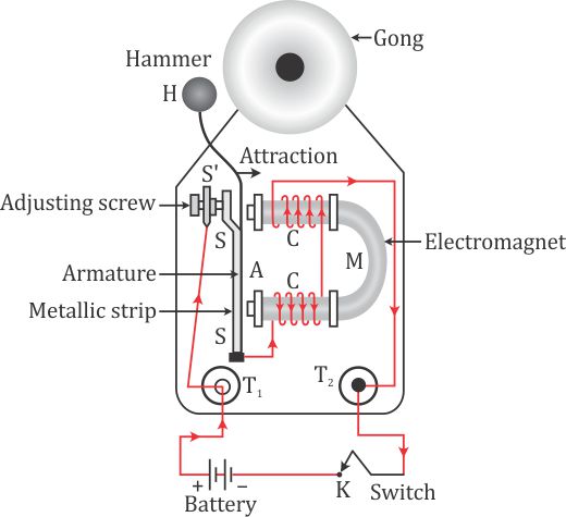
Electric bell
Solution B.7
(A)When current flows in a wire, it creates magnetic field around it.
(B) On reserving the direction of current in a wire, the magnetic field produced by it gets reversed.
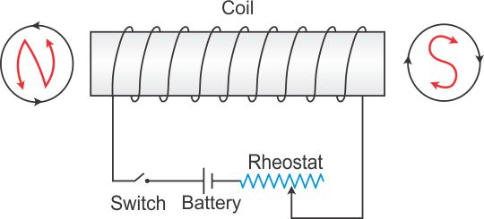
(C)A current carrying solenoid behaves like a bar magnet
(D)A current carrying solenoid when freely suspended, it always rest in north-south direction.
Solution C.1
Right hand thumb rule determines the direction of magnetic field around a current carrying wire.
It states that if we hold the current carrying conductor in right hand such that the thumb points in the direction of flow of current, then the fingers encircle the wire in the direction of the magnetic fields lines.
Solution C.2
A current carrying conductor produces a magnetic field around it and the magnetic needle in this magnetic field experience a torque due to which it deflects to align itself in the direction of magnetic field.
Solution C.3
Right hand thumb rule: If we hold the current carrying conductor in right hand such that the thumb points in the direction of flow of current, then the fingers encircle the wire in the direction of the magnetic fields lines.
Solution C.4
(a) A - North pole, B - South pole.
(b) The magnet will be repelled because the end of the solenoid near the north pole of magnet becomes the north pole as current at this face is anticlockwise and the two like poles repel.
Solution C.5
The magnetic field due to a solenoid can be made stronger by using:
(i) By increasing the number of turns of winding in the solenoid.
(ii) By increasing the current through the solenoid.
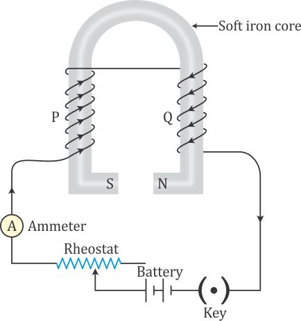
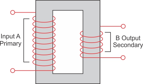
Solution C.6
From the given figure we can conclude that,
Number of turns in coil B > Number of turns in coil A.
And as we know, the strength of magnetic increases on increasing the number of turns in a coil.
Hence,
Current produced by coil A < Current produced by coil B.
∴ x < y
Here,
y = Deflection made by galvanometer connected to coil B
x = Deflection made by galvanometer connected to coil A
Solution C.7
A current carrying freely suspended solenoid at rest behaves like a bar magnet. It is because a current carrying solenoid behaves like a bar magnet. It align itself in north south direction.
Solution C.8
The needle of the compass will rest in in the direction of magnetic field due to solenoid at that point.
Solution C.9
(a)X-north pole, Y –south pole.
(b)By reducing resistance of circuit by mean of rheostat to increase current.
Solution C.10
An electromagnet is a temporary strong magnet made from a piece of soft iron when current flows in the coil wound around it. It is an artificial magnet.
The strength of magnetic field of an electromagnet depends on:
(i) Number of turns: The strength of magnetic increases on increasing the number of turns of winding in the solenoid.
(ii) Current: The strength of magnetic field increases on increasing the current through the solenoid.
Solution C.11
the strength of an electromagnet can be increased by following ways:
(i) By increasing the number of turns of winding in the solenoid.
(ii) By increasing the current through the solenoid.
Solution C.12
1.An electromagnet can produce a strong magnetic field.
2.The strength of the magnetic field of an electromagnet can easily be changed by changing the current in its solenoid.
Solution C.13
|
Electromagnet |
Permanent magnet |
|
It is made up of soft iron |
It is made up of steel. |
|
The magnetic field strength can be changed. |
The magnetic field strength cannot be changed.
|
|
The electromagnets of very strong field can be made. |
The permanent magnets are not so strong. |
Solution C.14
The soft iron bar acquires the magnetic properties only when an electric current flows through the solenoid and loses the magnetic properties as the current is switched off. That's why soft iron is used as the core of the electromagnet in an electric bell.
Solution C.15
If an a.c. source is used in place of battery, the core of electromagnet will get magnetized, but the polarity at its ends will change. Since attraction of armature does not depend on the polarity of electromagnet, so the bell will still ring on pressing the switch.
Solution C.16
The material used for making the armature of an electric bell is soft iron which can induce magnetism rapidly.
Solution D.1
Experiment:
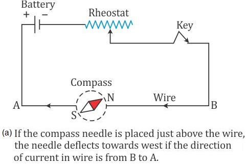
In Fig , AB is a wire lying in the north- south direction and connected to a battery through a rheostat and a tapping key. A compass needle is placed just below the wire. It is observed that
(1)When the key is open i.e., no current passes through the wire, the needle shows no deflection and it points in the N-S direction (i.e. along the earth's magnetic field). In this position, the needle is parallel to the wire as shown in Fig. (a).
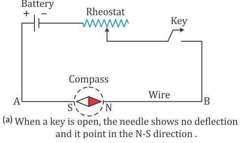
(2)When the key is pressed, a current passes in the wire in the direction from A to B (i.e. From
south to north) and the north pole(N) of the needle deflects towards the west [Fig. (b)].
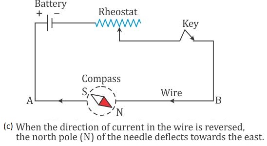
(3)When the direction of current in the wire is reversed by reversing the connections at the
terminals of the battery, North Pole (N) of the needle deflects towards the east [Fig. (c)].
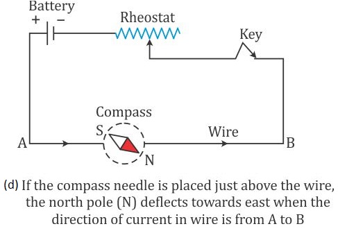
(4)If the compass needle is placed just above the wire, the North Pole (N) deflects towards
east when the direction of current in wire is from A to B [Fig. (d)], but the needle deflects
towards west as in fig (e), if the direction of current in wire is from B to A.
The above observations of the experiment suggest that a current carrying wire produces a
magnetic field around it.
Solution D.2
Solution D.3
Solution D.4
Solution D.5
(a) A - North pole, B - South pole.
(b) The north pole of compass needle will deflect towards west.
Reason: The end A of the coil behaves like north pole which repels north pole of compass needle towards west.
Solution D.6
Solution D.7
(a) Solenoid is a cylindrical coil of diameter less than its length.
(b) The device so obtained is electromagnet.
(c) It is used in electric relay.
Solution D.8
Solution D.9
(a)At A-south pole and at B-north pole.
(b)Polarity will also reverse. A will become north pole and B will become south pole.
(c)By increasing the number of turns
Solution D.10
Electro-magnetism Exercise Ex. 10B
Solution A.1
(a) Lorentz force
According to Lorentz's observation, a charge moving in a magnetic field in a direction other than the direction of the magnetic field experiences a force which was later termed as Lorentz force.
Solution A.2
(b) ![]()
The relation between the magnitude of the force (F) acting on a current-carrying wire which is placed in an external magnetic field (B) in the direction perpendicular to its length (l) is:
![]()
![]()
Solution A.3
(d) Nm-1 A-1
The relation between the magnitude of the force (F) acting on a current-carrying wire which is placed in an external magnetic field (B) in the direction perpendicular to its length (l) is:
![]()
![]()
Hence, the S.I. unit of magnetic field is ![]()
Solution A.4
(d) magnetic field
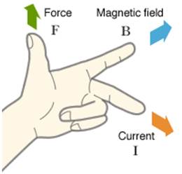
According to Fleming's left-hand rule, the forefinger indicates the direction of magnetic field thumb represents the direction of force and middle finger represents the direction of current.
Solution A.5
(c) from electrical to mechanical
In an electric motor, the energy transformation is from electrical to mechanical.
Note: An electric motor is a device which converts electrical energy into mechanical energy.
Solution A.6
(d) all of the above
The magnitude of force acting on a current carrying wire in a magnetic field in a direction perpendicular to its length is determined by:
· The current flowing through the wire.
· Magnetic field strength
· The length of the wire.
Solution A.7
(c) increasing the area of the coil
Increasing the area of a coil can increase its speed of rotation.
This is because a larger coil intersects with more magnetic field lines, resulting in a greater change in magnetic flux, higher induced EMF, and faster rotation.
Solution A.8
(c) reverse the direction of the current
A split ring commutator reverses the direction of the current.
Solution B.1
Direction of force is also reversed.
Solution B.2
Unit is: Newton/ampere x meter (or NA-1m-1).
Solution B.3
Electrical energy converts into mechanical energy.
Solution C.1
The magnitude of force on a current carrying conductor placed in a magnetic field depends on:
(i)On strength of magnetic field B.
(ii)On current I in the conductor.
(iii)On length of conductor.
Magnitude of force on a current carrying conductor placed in a magnetic field depends directly on these three factors.
Solution C.2
(a)When current in the conductor is in the direction of magnetic field force will be zero.
(b) When current in the conductor is normal to the magnetic field.
Solution C.3
Fleming's left hand rule: Stretch the forefinger, middle finger and the thumb of your left hand mutually perpendicular to each other. If the forefinger indicates the direction of magnetic field and the middle finger indicates the direction of current, then the thumb will indicate the direction of motion of conductor.
Solution C.4
Fleming's left hand rule: Stretch the forefinger, middle finger and the thumb of your left hand mutually perpendicular to each other. If the forefinger indicates the direction of magnetic field and the middle finger indicates the direction of current, then the thumb will indicate the direction of motion of conductor.
Solution C.5
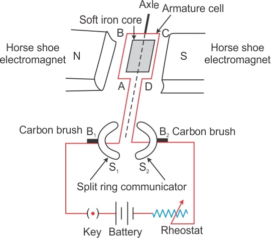
Electric motor: An electric motor is a device which converts the electrical energy into the mechanical energy.
Principle: An electric motor (dc motor) works on the principle that when an electric current is passed through a conductor placed normally in a magnetic field, a force acts on the conductor as a result of which the conductor begins to move and mechanical energy is obtained.
Solution C.6
The speed of rotation of an electric motor can be increased by:
(i)Increasing the strength of current.
(ii)Increasing the number of turns in the coil.
Solution C.7
Electric motor is used in electrical gadgets like fan, washing machine, juicer, mixer, grinder etc.
Solution D.1
(a)The coil will experience a torque due to which it will rotate.
(b) The coil will come to rest when their plane become normal to the magnetic field.
(c) (i) When plane of a oil is parallel to the magnetic field,
(ii) When plane of coil is normal to the magnetic field.
(d) The instrument which makes use of the principle stated above is d.c. motor.
Solution D.2
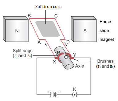
(a)The coil begins to rotate in anticlockwise direction.
(b) This is because, after half rotation, the arms AB and CD get interchanged, so the direction of torque on coil reverses. To keep the coil rotating in same direction, commutator is needed to change the direction of current in the coil after each half rotation of coil.
Solution D.3
Electro-magnetism Exercise Ex. 10C
Solution A.1
(c) magnetic flux
Electromagnetic induction is the phenomenon that occurs when the magnetic flux associated with a coil changes.
Solution A.2
(a) Faraday's law
Electromagnetic induction is based on Faraday's law.
Solution A.3
(b) Mechanical to electrical
In electromagnetic induction, energy transformation is from Mechanical to electrical.
Ex: In an A.C. generator, mechanical energy is converted into electrical energy using the principle of electromagnetic induction.
Solution A.4
(d) Both (a) and (b)
![]()
i.e., The magnitude of induced emf depends on:
1. number of turns in the coil.
2. rate of change of magnetic flux linked with each turn.
Solution A.5
(b) conservation of energy
Lenz’s law is based on conservation of energy.
Solution A.6
(c) the induced current
Fleming's right-hand rule states that the forefinger indicates the direction of the magnetic field, the thumb indicates the direction of the conductor motion, and the middle finger indicates the induced current.
Solution A.7
(b) e = e0 sin 2πnt
For an a.c. current, if the coil makes n rotations per second, the magnitude of induced e.m.f. at any instant t will be:
![]()
Similarly, the current will be expressed as
![]()
Here, e0 and i0 are maximum emf and current, respectively.
Solution A.8
(c) 50 Hz
In our Indian homes, the electric supply frequency is 50 Hz.
Solution A.9
(b) d.c., a.c.
A current of constant magnitude and unique direction is called d.c (Direct current) while a current changing its magnitude and direction periodically is called a.c (Alternating current).
Solution A.10
(d) Fleming's right hand rule
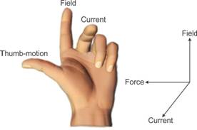
Statement: According to Fleming's right hand rule, if we stretch the thumb, middle finger and forefinger of our right hand mutually perpendicular to each other such that the forefinger indicates the direction of magnetic field and thumb indicates the direction of motion of conductor, then the middle finger will indicate the direction of induced current.
Solution A.11
(c) Ns > Np
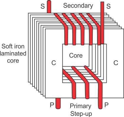
Hint: Since a step-up transformer is used to change a low voltage alternating e.m.f. to a high voltage alternating e.m.f. of same frequency, the number of turns in the secondary coil is more than the number of turns in the primary coil, i.e. ![]() .
.
Solution A.12
(c) decreases, increases
· A step-up transformer decreases the current and increase the a.c. voltage.
· Whereas a step-down transformer increases the current and decreases the a.c. voltage.
Solution A.13
(c)A transformer can be used with d.c.
Transformers increase or decrease the voltage in alternating current (a.c) circuits. Because the current is constant in d.c. circuits, thus induction is impossible.
Hence transformers are not used in d.c. circuits.
Solution B.1
(a)Mechanical energy changes to the electrical energy.
(b)Phenomenon is called electromagnetic induction.
Solution B.2
The current induced in a closed circuit only if there is change in number of magnetic field lines linked with the circuit.
Solution B.3
(1)Yes.
(2)Yes.
(3)Yes.
(4)No.
Solution B.4
Fleming's right hand rule determines the direction of current induced in the conductor.
Solution B.5
The number of rotations of the coil in one second or the speed of rotation of the coil.
Solution B.6
Mechanical, Electrical
Solution B.7
Mechanical energy changes into the electrical energy.
Solution B.8
The voltage of a.c. can be stepped up by the use of step-up transformer at the power generating station before transmitting it over long distances. It reduces the loss of electrical energy as heat in the transmission line wires. On the other hand, if d.c. is generated at the power generating station, its voltage cannot be increased for transmission, and so due to passage of high current in the transmission line wires, there will be a huge loss of electrical energy as heat in the line wires.
Solution B.9
The relation is following:
![]()
S stands for secondary and P stands for primary.
Solution B.10
(i)In a step-up transformer, the number of turns in the primary is less than the number of turns in the secondary.
(ii)The transformer is used in alternating current circuits.
(iii)In a transformer, the frequency of A.C. voltage remain same.
Solution B.11
Soft iron is used in all.
Solution C.1
Faraday's formulated two laws of electromagnetic induction:
(i)Whenever there is a change in the magnetic flux linked with a coil, an e.m.f. is induced. The induced e.m.f. lasts so long as there is a change in the magnetic flux linked with the coil.
(ii)The magnitude of the e.m.f. induced is directly proportional to the rate of change of the magnetic flux linked with the coil. If the rate of change of magnetic flux remains uniform, a steady e.m.f. is induced.
Solution C.2
Magnitude of induced e.m.f depend upon:
(i)The change in the magnetic flux.
(ii)The time in which the magnetic flux changes.
Solution C.3
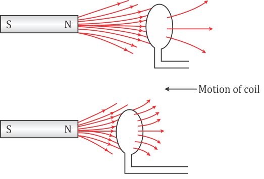
(a)When there is a relative motion between the coil and the magnet, the magnetic flux linked with the coil changes. If the north pole of the magnet is moved towards the coil, the magnetic flux through the coil increases as shown in above figure. Due to change in the magnetic flux linked with the coil, an e.m.f. is induced in the coil. This e.m.f. causes a current to flow in the coil if the circuit of the coil is closed.
(b)The source of energy associated with the current obtained in part (a) is mechanical energy.
Solution C.4
Fleming's right hand rule: Stretch the forefinger, middle finger and the thumb of your right hand mutually perpendicular to each other. If the forefinger indicates the direction of magnetic field and the thumb will indicates the direction of motion of conductor, then the middle finger indicates the direction of induced current.
Solution C.5
Lenz's law: It states that the direction of induced e.m.f. (or induced current) is such that it always tends to oppose the cause which produces it.
Solution C.6
When a coil has a large number of turns, then magnitude of induced e.m.f. in the coil become more and then by Lenz's law it will oppose more.
Solution C.7
So that the mechanical energy spent in producing the change, is transformed into the electrical energy in form of induced current.
Solution C.8
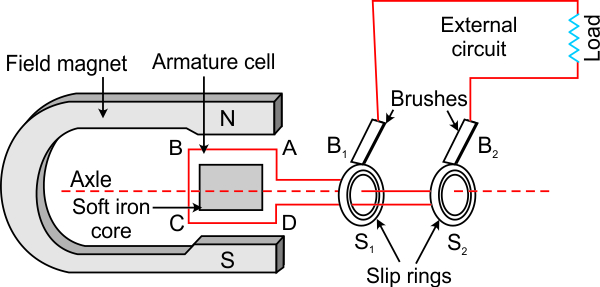
An A.C. generator works on the principle of 'electromagnetic induction'.
Statement: Whenever a coil is rotated in a magnetic field, the magnetic flux linked with the coil changes, and therefore, an EMF is induced between the ends of the coil. Thus, a generator acts like a source of current if an external circuit containing load is connected between the ends of its coil.
Solution C.9
(a)In an a.c generator, if the speed at which the coil rotates is doubled, the frequency is also doubled.
(b) Maximum output voltage is also doubled.
Solution C.10
Two ways in an a.c generator to produce a higher e.m.f. are:
(1)By increasing the speed of rotation of the coil.
(2)By increasing the number of turns of coil.
Solution C.11
Two dissimilarities between D.C. motor and A.C. generator:
|
A.C. Generator
|
D.C. Motor
|
|
1. A generator is a device which converts mechanical energy into electrical energy.
|
1. A D.C. motor is a device which converts electrical energy into mechanical energy.
|
|
2. A generator works on the principle of electromagnetic induction.
|
2. A D.C. works on the principle of force acting on a current carrying conductor placed in a magnetic field.
|
Similarity: Both in A.C generator and D.C motor, a coil rotates in a magnetic field between the pole pieces of a powerful electromagnet.
Solution C.12
The purpose of the transformer is to step up or step down the a.c. voltage.
No, a transformer cannot be used with a direct current source.
Solution C.13
The magnitude of an induced e.m.f. in the secondary coil of a transformer depends on the following two factors.
a) The ratio of number of turns in the secondary coil to the number of turns in the primary coil.
b) The magnitude of e.m.f. applied in the primary coil.
Solution C.14
The device is step up transformer.
It works on the principle of electromagnetic induction.
Solution C.15
(i) In case of a step-up transformer, thicker wire is used in the primary coil as compared to that in the secondary coil.
(ii) In a step-down transformer, the wire in the secondary coil is thicker than in the primary coil.
The use of thicker wire reduces its resistance and therefore reduces the loss of energy as heat in the coil. In step up NS > NP therefore ES > EP, but Is < IP i.e., more current flows in the primary coil. The reverse is the case of a step-down transformer. Thus, the thickness of the wire is chosen accordingly.
Solution C.16
The secondary windings of a transformer in which the voltage is stepped down are usually made up of thicker than the primary because more current flows in the secondary coil. The use of thicker wire reduces its resistance and therefore the loss of energy as heat in the coil.
Solution C.17
To reduce the energy losses due to eddy currents.
Solution C.18
The energy loss in a transformer is called 'copper loss'.
Copper losses: Primary and secondary coils of a transformer are generally made of copper wire. These copper wires have resistance. When current flows through these wires, a part of the energy is lost in the form of heat. This energy lost through the windings of the transformer is known as copper loss.
This loss can be minimized by using thick wires for the windings. Use of thick wire reduces its resistance and therefore reduces the loss of energy as heat in the coil.
2. Loss due to eddy current.It can be minimised by using laminated core.
Solution C.19
|
Step up transformer
|
Step down transformer |
|
It increases the a.c. voltage and decrease the current. |
It decreases the a.c. voltage and increase the current. |
|
The wire of primary coil is thicker than that in the secondary coil.
|
The wire in the secondary coil is thicker than that in the primary coil.
|
Solution C.20
(i) Step-up transformer.
In power generating stations the alternating current generated is first stepped up from 11 kV to 132 kV.
(ii) Step-down transformer.
At the power sub-station, voltage is stepped down before its distribution to the consumers.
Transformers are used so as to reduce the loss of energy in the form of heat in the line wires used for transmission.
Solution D.1
(a) Electromagnetic induction: whenever there is change in number of magnetic field lines associated with conductor, an electromotive force is developed between the ends of the conductor which lasts as long as the change is taking place.
(b) Demonstration of the phenomenon of electromagnetic induction:
In the figure:
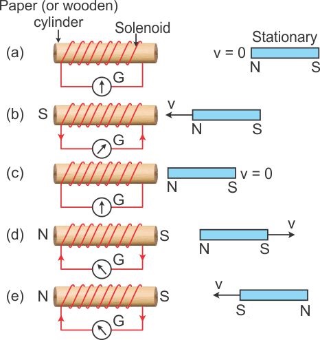
(i)When the magnet is stationary there is no deflection in galvanometer. The pointer read zero. [Fig. (a)]
(ii)when the magnetwith north pole facing the solenoid is moved towards the solenoid, the galvanometer shows a deflection towards the right showing that a current flows in the solenoid in the direction as shown in [Fig (b)]
(iii) As the motion of magnet stops, the pointer of the galvanometer comes to the zero position [Fig (c)]. This shows that the current in the solenoid flows as long as the magnet is moving.
(iv)If the magnet is moved away from the solenoid, the current again flows in the solenoid, but now in a direction opposite to that shown in [Fig. (b)] and therefore the pointer of the galvanometer deflects towards left[ Fig. (d)].
(v)If the magnet is moved away rapidly i.e. with more velocity, the extent of deflection in the galvanometer increases although the direction of deflection remains the same.It shows that more current flows now.
(vi)If the polarity of the magnet is reversed and then the magnet is brought towards the solenoid, the current in solenoid flows in the direction opposite to that shown in Fig (b) and so the pointer of galvanometer deflect towards left [Fig. (e)].
Solution D.2
(a) Induced current can be produced by following activity:
(i)When the magnet is stationary there is no deflection in galvanometer. The pointer read zero. [Fig (a)]
(ii)When the magnetwith north pole facing the solenoid is moved towards the solenoid, the galvanometer shows a deflection towards the right showing that a current flows in the solenoid in the direction as shown in Fig (b)
(iii) As the motion of magnet stops, the pointer of the galvanometer to the zero position [Fig (c)]. This shows that the current in the solenoid flows as long as the magnet is moving.
(iv)If the magnet is moved away from the solenoid , the current again flows in the solenoid , but now in the direction opposite to that shown in [Fig. (b)] and therefore the pointer of the galvanometer deflects towards left [Fig. (d)].
(v)If the magnet is moved away rapidly i.e. with more velocity, the extent of deflection in the galvanometer increases although the direction of deflection remains the same.It shows that more current flows now.
(vi)If the polarity of the magnet is reversed and then the magnet is brought towards the solenoid, the current in solenoid flows in the direction opposite to that shown in Fig (b) and so the pointer of galvanometer deflect towards left [Fig. (e)].
(b) Magnitude of induced e.m.f depend upon:
(i)The change in the magnetic flux.
(ii)The time in which the magnetic flux changes.
(c) The direction of induced e.m.f depends on whether there is an increase or decrease in the magnetic flux.
Solution D.3
Lenz's law implies the law of conservation of energy. It shows that the mechanical energy spent in doing work, against the opposing force experienced by the moving magnet, is transformed into the electrical energy due to which current flows in the solenoid.
Solution D.4
(i) When the coil is moved in the direction of magnet the North pole generates near this end and current starts flowing from A to B.
(ii) Lenz's law.
(iii) (a)Current is directly proportional to the number of turns, therefore it will also become 2 times
(b) Current becomes thrice.
Solution D.5
(i)The pointer of galvanometer deflects towards left. The deflection lasts so long as the coil moves.
(ii)(a) Deflection becomes twice (b) Deflection becomes thrice.
Solution D.6
Solution D.7
Step up transformer:
Solution D.8
Step-up transformer: The step-up transformer is used to change a low voltage alternating e.m.f. to a high voltage alternating e.m.f. of same frequency.
Working: When the terminals of primary coil are connected to the source of alternating e.m.f., a varying current flows through it which also produces a varying magnetic field in the core of the transformer. Thus, the magnetic field lines linked with the secondary coil vary and induce an e.m.f. in the secondary coil. The induced e.m.f. varies in the same manner as the applied e.m.f. in the primary coil varies, and thus, has the same frequency as that of the applied e.m.f.
The magnitude of e.m.f. induced in the secondary coil depends on the 'turns ratio' and the magnitude of the applied e.m.f.
For a transformer,

Two characteristics of the primary coil as compared to its secondary coil:
1. The number of turns in the primary coil is less than the number of turns in the secondary coil.
2. A thicker wire is used in the primary coil as compared to that in the secondary coil.
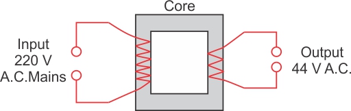
Solution D.9
The device is step down transformer.
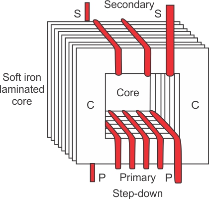
Working: In a step down transformer, the number of turns in secondary coil are less than the number of turns in the primary coil i.e., turns ratio nS/NP<1.
As Es/Ep = NS/NP.
So Es/Eps is less than Ep.
Two uses of step down transformer are:
(i)With electric bells
(ii)At the power sub-stations to step-down the voltage before its distribution to the customers.
Solution D.10
(a)
(b) A is the primary coil. B is the secondary coil.
We have drawn laminated core in the diagram.
(c) The material of this part is soft iron.
(d) This transformer a step-down transformer because the number of turns in primary coil is much greater than that in the secondary coil.
Solution D.11
(a) Soft iron core is used. The core is made up from the thin laminated sheets of soft iron of T and U shape, placed alternately one above the other and insulated from each other by paint or varnish coating over them.
(b)
(c) It is a step down transformer.
Solution D.12
(a) When the key is closed, the current flows from B to A and the magnetic field direction just below the conductor is towards the East. Therefore, the magnetic needle will deflect towards the East.
(b) When current passes through the conductor the magnetic field is produced around it, as a result we see the deflection.
(c) In the second case, when a magnetic needle is kept just above the conductor, when the key is closed the direction will reverse, i.e., from B to A. Using the right-hand thumb rule just above the conductor, the magnetic field generated points west. As a result, the needle will deflect to the west.
(d) Magnetic sensor.
Solution D.13
A transformer is a device by which the amplitude of an alternating e.m.f. can be increased or decreased.
For an ideal transformer , when there is no loss of energy , the output power is equal to input power i.e.,
Power in secondary coil = power in primary coil
![]()
Solution E.1
Given that:
Decrease in the flux = 0.005 - 0 = 0.005 weber,
Number of tuns = 100 turns and
Time = 5 second
e.m.f. induced e = N × Rate of increase of magnetic flux
------------------= ![]()
∴ e.m.f. induced e = 0.1 V = 100 mV
Solution E.2
No. of turns in primary coil Np =800
No. of turns in secondary coil Np=8.
Input supply voltage Ep = 220 V.
We know that
![]()
 =
= ![]()
Es =2.2 V.
Solution E.3
Input ac voltage Ep = 240 V.
Number of turns in primary coil Np = 4800
No. of turns in secondary coil Ns=?
Output voltage Es = 8 V.
We know that
![]()
 =
= ![]()
Number of turns in secondary coil = 160.
Solution E.4
(a)We know that
![]()
So turns ratio
![]() =
= ![]()
(b)Output current Is= 2A, Es =44V.
Input current Ip =?,Ep =220 V.
We know that =Es Is =EpIp
Ip =![]()