Class 10 SELINA Solutions Physics Chapter 8 - Current Electricity
Current Electricity Exercise Ex. 8A
Solution A.16
(d) Nichrome wire
Nichrome wire is an ohmic resistance.
Hint: Substances that obey Ohm's law are called Ohmic resistors.
Solution A.17
(c) Carbon
For carbon, resistance decreases with an increase in temperature.
Hint: For semiconductors such as carbon and silicon, the resistance and resistivity decreases with the increase in temperature.
Solution B.1
Expression :
![]()
![]() - resistivity
- resistivity
R – resistance
l – length of conductor
A – area of cross-csection
Solution B.2
Metal < Semiconductor < Insulator
Solution B.3
Manganin
Solution B.4
(i) A wire made of tungsten is used for filament of electric bulb because it has a high melting point and high resistivity.
(ii) A nichrome wire is used as a heating element for a room heater because the resistivity of nichrome is high and increase in its value with increase in temperature is high.
Solution B.5
Superconductor
Solution C.1
Current is defined as the rate of flow of charge.
I=Q/t
Its S.I. unit is Ampere.
Solution C.2
Electric potential at a point is defined as the amount of work done in bringing a unit positive charge from infinity to that point. Its unit is the volt.
Solution C.3
The potential difference between two points is equal to the work done in moving a unit positive charge from one point to the other.
It's S.I. unit is Volt.
Solution C.4
One volt is the potential difference between two points in an electric circuit when 1 joule of work is done to move charge of 1 coulomb from one point to other.
Solution C.5
a. Current is a scalar quantity. The direction of current conveys that the flow of electrons is opposite to the direction of flow of current.
b. Potential is also a scalar quantity. The positive sign of potential conveys that work has to be done on the positive test charge against the repulsive force due to the positive charge in bringing it from infinity. The negative sign of potential conveys that work is done on the negative test charge by the attractive force.
Solution C.6
It is the property of a conductor to resist the flow of charges through it. It's S.I. unit is Ohm.
Solution C.7
(a) Particles responsible for the flow of current in a metallic wire are free electrons.
(b) In metals, free electrons are the moving charges that result in the conduction of electricity. If 'n' electrons pass through the metallic conductor in time 't', then the total charge that has flown is given by Q (charge) = n x e (charge on an electron).
(c) A metal includes free electrons and fixed positive ions.
Positive ions give away their valence electrons and thus attain a positive charge.
Electrons are free for movement, but positive ions do not move; thus, when a potential difference is applied across the circuit, and when free electrons begin to move, they collide with these fixed ions.
This collision is the major cause of resistance offered by the metallic wire in the flow of current through it.
Solution C.8
(a)The law is called Ohm's law. It states that the current flowing through the conductor is directly proportional to the potential difference across the ends of a conductor given the temperature remains constant.
(b) Temperature should remain constant.
Solution C.9
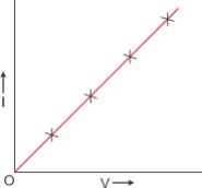
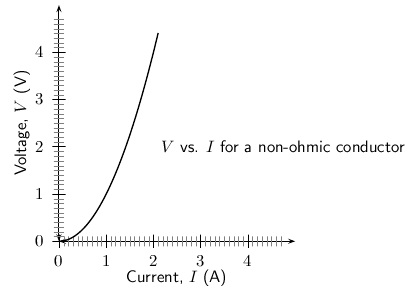
(1) Ohmic resistor obeys ohm's law i.e., V/I is constant for all values of V or I; whereas Non-ohmic resistor does not obey ohm's law i.e., V/I is not same for all values of V or I.
(2) In Ohmic resistor, V-I graph is linear in nature whereas in non-ohmic resistor, V-I graph is non-linear in nature.
Solution C.10
Ohmic: (b), Non-Ohmic: (a)
Only for (a) the I-V graph is a straight line or linear while for (a), the graph is a curve.
Solution C.11
Resistance of a wire is directly proportional to the length of the wire.
![]()
The resistance of a conductor depends on the number of collisions which the electrons suffer with the fixed positive ions while moving from one end to the other end of the conductor. Obviously the number of collisions will be more in a longer conductor as compared to a shorter conductor. Therefore, a longer conductor offers more resistance.
Solution C.12
With the increase in temperature of conductor, both the random motion of electrons and the amplitude of vibration of fixed positive ions increase. As a result, the number of collisions increases. Hence, the resistance of a conductor increases with the increase in its temperature.
The resistance of filament of a bulb is more when it is glowing (i.e., when it is at a high temperature) as compared to when it is not glowing (i.e., when it is cold).
Solution C.13
Iron wire will have more resistance than copper wire of the same length and same radius because resistivity of iron is more than that of copper.
Solution C.14
(i) Resistance of a wire is directly proportional to the length of the wire means with the increase in length resistance also increases.
![]()
(ii) Resistance of a wire is inversely proportional to the area of cross-section of the wire. If area of cross-section of the wire is more, then resistance will be less and vice versa.
![]()
(iii) Resistance increases with the increase in temperature since with increase in temperature the number of collisions increases.
(iv) Resistance depends on the nature of conductor because different substances have different concentration of free electrons.Substances such as silver, copper etc. offer less resistance and are called good conductors; but substances such as rubber, glass etc. offer very high resistance and are called insulators.
Solution C.15
The resistivity of a material is the resistance of a wire of that material of unit length and unit area of cross-section.
Its S.I. unit is ohm metre.
Solution C.16
(a) The specific resistance of a wire depends on the material of the substance and the temperature of the substance.
(b) Specific resistance depends on the material of the wire and not its dimensions. Hence, both the wires will have the same specific resistance .
Solution C.17
Specific resistance of a semiconductor decreases with increase in temperature.
Solution C.18
Resistance is directly proportional to the length and inversely proportional to the square of radius. Specific resistance is independent on the dimensions of a wire.
Solution C.19
(a) The materials used for making connection wires are copper or aluminium. These materials are chosen because they have small specific resistance.
(b) A connection wire should be thick so that it offers negligible resistance to the flow of current through the circuit.
Solution C.20
Manganin is used for making the standard resistor because its resistivity is quite large and the effect of change in temperature on their resistance is negligible.
Solution C.21
Generally fuse wire is made of an alloy of lead and tin because its resistivity is high and melting point is low.
Solution C.22
A superconductor is a substance of zero resistance at a very low temperature. Example: Mercury at 4.2 K.
Solution D.1
It states that electric current flowing through a metallic wire is directly proportional to the potential difference V across its ends provided its temperature remains the same. This is called Ohm's law.
V = IR
Solution D.2
(a)
(b) Slope of VI graph represents the resistance.
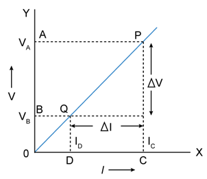
Solution D.3
The slope of I-V graph (=![]() ) is equal to the reciprocal of the resistance of the conductor, i.e.
) is equal to the reciprocal of the resistance of the conductor, i.e.
![]()
Solution D.4
Ohmic Resistor: An ohmic resistor is a resistor that obeys Ohm's law. For example: all metallic conductors (such as silver, aluminium, copper, iron etc.)
From above graph resistance is determined in the form of slope.
Solution D.5
The conductors which do not obey Ohm's Law are called non-ohmic resistors. Example: diode valve.
Solution D.6
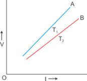
In the above graph, T1 ![]() T2. The straight line A is steeper than the line B, which leads us to conclude that the resistance of conductor is more at high temperature T1 than at low temperature T2. Thus, we can say that resistance of a conductor increases with the increase in temperature.
T2. The straight line A is steeper than the line B, which leads us to conclude that the resistance of conductor is more at high temperature T1 than at low temperature T2. Thus, we can say that resistance of a conductor increases with the increase in temperature.
Solution D.7(a)
Resistance of a wire is inversely proportional to the area of cross-section of the wire.
![]()
![]()
This means if a wire of same length, but of double radius is taken, its resistance is found to be one-fourth.
Solution D.7(b)
Resistance is directly proportional to the length and inversely proportional to the area of cross-section. The thicker wire has more area, and hence the resistance of the other wire will be more than that of the thicker wire.
Solution E.1

Solution E.2
Given that,
Current , I = 3.2 mA = 3.2 x 10⁻³ A
Charge, Q = -1.6 x 10⁻¹⁹ coulomb
t=1 sec
Now,
I = Q/t → Q = I x t
Q = 3.2 x 10-3 x 1
No. of electrons = 3.2 x 10⁻³/1.6 x 10-19
= 2 × 10¹⁶
Solution E.3
Current (I) = 300 mA = 0.3 A
Resistance (R) = 20 ohm
Potential Difference (V) = ?
Now,
According to Ohm's Law :
V = IR
V = 0.3 x 20 = 6 V
Solution E.4
Current (I) = 1.2 A
Potential Difference/Voltage (V) = 6.0 V
Resistance (R) = ?
According to Ohm's Law :
V=IR
Then R = V/I
R = 6 / 1.2
R = 5 Ohm
Solution E.5
Potential Difference/Voltage (V) = 12 V
Current (I) = 2 A
Resistance (R) = ?
According to Ohm's Law :
V=IR
Then R = V/I
R = 12 / 2
R = 6 Ohm
Resistance will be less when the bulb is not glowing.
Solution E.6
Potential Difference/Voltage (V) = 3 V
Resistance (R) = 5 ohm
Current (I) = ?
According to Ohm's Law :
V=IR
Then I = V/R
I=3/5 =0.6 A
Solution E.7
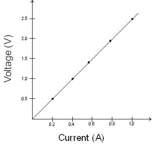
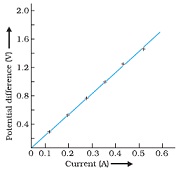
(a) 1.25 V
(b) 0.3 A
(c) The graph is linear so resistance can be found from any value of the given table. For instance :
When V=2.5 Volt
Current is I=1.0 amp
According to ohm's law :
R=V/I
R=2.5/1.0 = 2.5 ohm
Solution E.8
(i)For wire of radius r1 :

(ii)For wire of radius r2 :


(ii) Since the material of the two wires is same, so their resistivities will also be same i.e., ![]()
Solution E.9

Solution E.10
Resistance (R) = 3 ohm
Length l = 10 cm
New Length (l') = 30 cm = 3 x l
![]()
New Resistance :
With stretching length will increase and area of cross-section will decrease in the same order
![]()
Therefore,

Solution E.11
Resistance (R) = 9 ohm
Length l = 30 cm
New Length (![]() ) = 30 cm = 3/l = 10 cm
) = 30 cm = 3/l = 10 cm
![]()
New Resistance :
With change in length, there will be change in area of cross-section also in the same order.

R' = 1 ohm
Solution E.12
Resistance (R) = 2 ohm
Resistivity (![]() ) = 1.7 x 10⁻⁸ W metre
) = 1.7 x 10⁻⁸ W metre
Radius (r) = 1 mm = 10-3 m
Length (l) = ?
Now,

Solution E.13
According to Ohm's law,

Resistance of the wire increases with increase in temperature. So the difference arises because the temperature of the filament increased.
Solution A.1
(b) Coulomb
The S.I. unit of charge is Coulomb.
Solution A.2
(d) - 1.6 × 10⁻¹⁹ C
The charge on an electron is - 1.6 × 10⁻¹⁹ C
Solution  A.3
(a) 6.25 × 10¹⁸
Q= ne
∴ n = 1 / (1.6 × 10⁻¹⁹) = 6.25 × 10¹⁸
Solution A.4
(c) ammeter, series
The current in a circuit is measured by ammeter connecting it in series.
Solution A.5
(a) I =ne/t
If n electrons pass through a cross-section of a conductor in time t, then the current in a conductor is I = ne/t.
Solution A.6
(c) V = W/Q
We know that,
W = QV
Thus,
V = W/Q
Electric potential (V) represents the amount of work (W) done per unit charge (Q) to move a test charge from a reference point to a specific point (P) in an electric field.
Solution A.7
(a) 1 joule
W = QV = 1 V × 1C = 1 J
Solution A.8
(b) voltmeter, parallel
The potential difference between two points in an electric circuit is measured by a voltmeter which is connected in parallel with the circuit.
Solution A.9
(c) resistance
Resistance is the obstruction offered to the flow of current by a wire.
Solution A.10
(d) All of the above
According to Ohm’s law,
Current I is directly proportional to resistance R.
⟹I ∝ V
⟹V/I = constant
⟹V = IR
R is the proportionality constant called resistance.
Solution  A.11
(c) volt/ampere
We know,
V = IR
R = V/I
SI unit of resistance (R) is ohm.
SI unit of voltage (V) is volt.
SI unit of current (I) is ampere.
Thus, ohm = volt/ampere
Solution A.12
(c) ohm-1
The conductance is the reciprocal of resistance.
Thus, the unit of conductance is ohm-1.
Solution A.13
(c) solar cell
This is a resistor that does not obey the Ohm's Law. The resistance of a non-ohmic resistor changes with the voltage or current applied.
Solution A.14
(d) all of the above
The resistance of a conductor depends on:
1. the temperature of the conductor
2. the thickness of the conductor
3. the length of the conductor
Solution A.15
(d) 9R
R = ρ l/A
When the length of the wire is increased by 3l by stretching, its cross-section area is reduced to A/3.
Thus,
R’ = ρ (3l)/(A/3) = 9 (ρ l/A) = 9R
Solution A.18
(c) Constantan
Standard resistors are made of constantan.
Solution A.19
(d) Both (a) and (c)
The properties for which nichrome wire is used in heating appliances is/are:
· Specific resistance is high.
· Resistance increases with an increase in temperature.
Solution A.20
(d) both (a) and (c)
A superconductor is a substance of infinite conductance and zero resistance.
Current Electricity Exercise Ex. 8B
Solution A.5
(c) Current is same in each resistance
In series combination of resistances, current is same in each resistance.
Hint: In a series combination, the current has a single path for its flow. Hence, the same current passes through each resistor.
Solution A.6
(a) P.D. is same across each resistance
In parallel combination of resistances, P.D. is same across each resistance.
Hint: In parallel combination, the ends of each resistor are connected to the ends of the same source of potential. Thus, the potential difference across each resistance is same and is equal to the potential difference across the terminals of the source (or battery).
Solution A.7
(a) and (d)
Solution:

Solution B.1
(a)Total Resistance in series:
![]()
(b)Total Resistance in parallel:
![]()
Solution B.2
(a) series
(b) parallel
(c) parallel
(d) series
Solution C.1
|
e.m.f. of cell |
Terminal voltage of cell |
|
1.It is measured by the amount of work done in moving a unit positive charge in the complete circuit inside and outside the cell. |
1. It is measured by the amount of work done in moving a unit positive charge in the circuit outside the cell. |
|
2.It is the characteristic of the cell i.e., it does not depend on the amount of current drawn from the cell |
2. It depends on the amount of current drawn from the cell. More the current is drawn from the cell, less is the terminal voltage. |
|
3.It is equal to the terminal voltage when cell is not in use, while greater than the terminal voltage when cell is in use. |
3. It is equal to the emf of cell when cell is not in use, while less than the emf when cell is in use. |
Solution C.2
Internal resistance of a cell depends upon the following factors:
(i) The surface area of the electrodes: Larger the surface area of the electrodes, less is the internal resistance.
(ii) The distance between the electrodes: More the distance between the electrodes, greater is the internal resistance.
Solution C.3
(a) Total resistance = R + r
(b) Current drawn from the circuit :
As we know that,
![]() =V+v
=V+v
= IR + Ir
=I(R+r)
I = e / (R + r)
(c) p.d. across the cell : ![]()
(d) voltage drop inside the cell: 
Solution C.4
(a) Terminal voltage is less than the emf : Terminal Voltage < e.m.f.
(b) e.m.f. is equal to the terminal voltage when no current is drawn.
Solution C.5
For the same change in I, change in V is less for the straight line A than for the straight line B (i.e., the straight line A is less steeper than B), so the straight line A represents small resistance, while the straight line B represents more resistance. In parallel combination, the resistance decreases while in series combination, the resistance increases. So A represents the parallel combination.
Solution D.1
e.m.f.: When no current is drawn from a cell, the potential difference between the terminals of the cell is called its electro-motive force (or e.m.f.).
Terminal voltage: When current is drawn from a cell, the potential difference between the electrodes of the cell is called its terminal voltage.
Internal Resistance: The resistance offered by the electrolyte inside the cell to the flow of electric current through it is called the internal resistance of the cell.
Solution D.2
When the electric cell is in a closed circuit the current flows through the circuit. There is a fall of potential across the internal resistance of the cell. So, the p.d. across the terminals in a closed circuit is less than the p.d. across the terminals in an open circuit by an amount equal to the potential drop across the internal resistance of the cell.
Solution D.3
If current I is drawn from the battery, the current through eac resistor will also be I.
On applying Ohm's law to the two resistors separately, we further
have
V1 = I R1
V2 = I R2
V=V1 + V2
IR = I R1+ I R2
R= R1+ R2
Total Resistance in series R :
![]()
Solution D.4
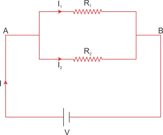
On applying Ohm's law to the two resistors separately, we further
Have
I1 = V / R1
I2 = V / R2
I = I1 + I2

Solution E.1
Given that,
R = 8 ohm
r = 2 ohm
ε = 4 V
Now,
(i) When key is open
Ammeter reading, I = 0
Voltage, V = ![]() - Ir
- Ir
V = 4 - 0 x 2 = 4 volt
(ii) When key is closed
Ammeter reading:
I = ε /(R+r)
I = 4 / (8 + 2) = 4 / 10 = 0.4 amp
Voltage reading:
Voltage, V = ε - Ir
V = 4 - 0.2 x 2 = 4 - 0.4 = 3.2 V
Solution E.2
Given that,
![]() = 6 V
= 6 V
I = 3 A
V = 5.4 V
Now,
Internal resistance, r = (e - V) / I
r = (6.0 V - 5.4 V) / 3 A
r = 0.6 V / 3 A
r = 0.2 Ω
Solution E.3
(a) ![]() = 1.8 V
= 1.8 V
Total Resistance = 2 + 4.5 + 0.7 = 7.2 W
I=?
I=![]() / R (total resistance)
/ R (total resistance)
I = 1.8 / 7.2 = 0.25 A
(b) Current (calculated in (a) part) I = 0.25 A
Now, total resistance excluding internal resistance = 4.5 + 0.7 = 5.2 ohm
V = IR = 0.25 x 5.2 = 1.3 V
Solution E.4
Solution E.5
In first case
I=1 A, R=1.9 ohm
![]() =I(R+r)=1(1.9+r)
=I(R+r)=1(1.9+r)
![]() =1.9+r------------(1)
=1.9+r------------(1)
In second case
I=0.5 A, R=3.9 ohm
![]() =I(R+r)=0.5(3.9+r)
=I(R+r)=0.5(3.9+r)
![]() =1.95+0.5r----------------(2)
=1.95+0.5r----------------(2)
From eq. (1) and (2),
1.9+r=1.95+0.5r
r=0.05/0.5=0.1 ohm
Substituting value of r
![]() =1.9+r=1.9+0.1=2 V
=1.9+r=1.9+0.1=2 V
Solution E.6


Solution E.7
R1 = 5 ohm
R2 = 5 ohm
R3 = 5 ohm
R4 = 5 ohm
For the parallel combination of resistors,


Solution E.8
![]()

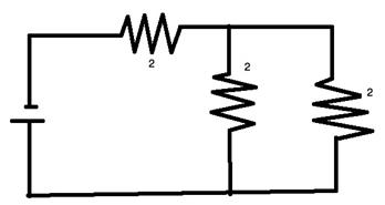
Solution E.9
A parallel combination of two resistors, in series with one resistor.
R1 = 2 Ω
R2 = 2 Ω
R3 = 2 Ω

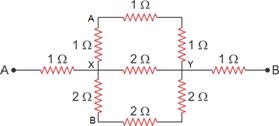
Solution E.10
For parallel resistances
![]()
Therefore
![]()
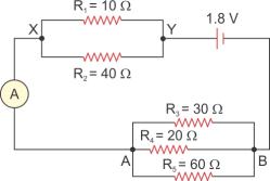
Solution E.11
Resistance of each set :
r1 = 2 + 2 + 2 = 6 ohm
r2 = 2 + 2 + 2 = 6 ohm
r3 = 2 + 2 + 2 = 6 ohm
r4 = 2 + 2 + 2 = 6 ohm
Now these resistances are arranged in parallel :

Solution E.12
r1 = 4 ohm
r2 = 8 ohm
r3 = x ohm
r4 = 5 ohm
r=4 ohm

Solution E.13

Solution E.14
Wire cut into three pieces means new resistance = 27/3 = 9
Now three resistance connected in parallel :

Solution E.15
Now, the circuit diagram for the given case will be as shown below,

Let,
R1 = 1 Ω
R2 = 6 Ω
R3 = 12 Ω
Now,

Solution E.16
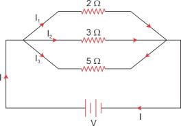
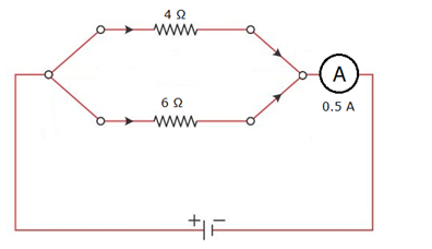
Solution E.17
R1=3+2 = 5 ohm
R2=30 W
R3=6+4 = 10 ohm
R1 , R2 and R3 are connected in parallel

Solution E.18
(a) R1=2+2+2 = 6ohm
R2=2ohm
R1 and R2 are connected in parallel

(b) R1=2+2 = 4 ohm
R2=2+2=4 W
R1 and R2 are connected in parallel

Solution E.19
(a) R1=3+3=6 W
R2=3 W
R1 and R2 are connected in parallel

(b) As calculated above R=2 ohm
R3 = 3 ohm
R4 = 3 ohm
R'=R+R3+R4=2+3+3 = 8 ohm
Solution E.20


Solution E.21
(a)
R1=6 ohm
R2=4 ohm
R = R1 + R2 = 6 + 4 = 10 ohm
V=20 V
I=V/R = 20/10 = 2 A
(b) R = 6 W
I = 2 A
V = ?
V = IR = 6 x 2 = 12 V
Solution E.22
a. Circuit diagram
b. Equivalent resistance of the circuit:

Hence, the emf of the cell is

Therefore, current through each resistor is

Solution E.23
For resistor A :
R=1 ohm
V=2 V
I=V/R = 2/1 = 2A
For resistor B :
R = 2 ohm
V = 2 V
I=V/R = 2/2 = 1A
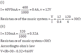
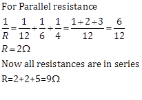
Solution E.24
(a)
V=4 V
I=0.4 A
Total Resistance R'=?
R' = V/I = 0.4/4 = 10 ohm
(b)
R1= 20 ohm
R' = 10 ohm

(c)
R=20 ohm
V=4 V
I=V/R = 4/20 = 0.2 A
Solution E.25
(a)
Resistance of 1m of wire = 3 ohm
Resistance of 1.5 m of wire = 3 x 1.5 = 4.5 W

(b)
I=2 A
V=IR = 2 x 4.5 = 9 V
(c)
R=3 ohm for 1 m
For 5 m : R=3 x 5 = 15 ohm
But Area A is double i.e. 2A and Resistance is inversely proportional to area so Resistance will be half.
R=15/2 = 7.5 ohm
Solution E.26
In parallel R = ½ + ½ = 1 ohm
I = 1.2 A
![]() =I(R+r) = 1.2(1+r)= 1.2 + 1.2 r
=I(R+r) = 1.2(1+r)= 1.2 + 1.2 r
In series R = 2+2=4 ohm
I=0.4 A
![]() =I(R+r) = 0.4(4+r) = 1.6 + 0.4 r
=I(R+r) = 0.4(4+r) = 1.6 + 0.4 r
It means :
1.2 + 1.2 r = 1.6 + 0.4 r
0.8 r = 0.4
r = 0.4 / 0.8 = ½ = 0.5 ohm
(i) Internal resistance r = 0.5 ohm
(ii) ![]() =I(R+r) = 1.2(1+0.5) = 1.8 V
=I(R+r) = 1.2(1+0.5) = 1.8 V
Solution E.27
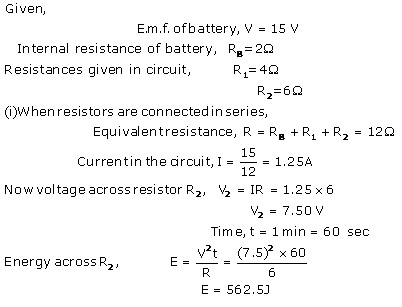
Given that,
Emf of battery, ε = 16 V
internal resistance of battery, r = 2 Ω
R1 = 3 Ω
R2 = 6 Ω
(a)
Now,
1/R = 1/R1 + 1/R2
= 1/R = 1/3 + 1/6
= 1/R = 1/2
= R = 2 Ω
Total circuit resistance,
r' = r + R
= 2 Ω + 2 Ω
= 4 Ω
Current through the battery,
I = E / r'
= 16 V / 4 Ω
= 4 A
(b) P.D. between the terminals of the battery,
V = E - I r
= 16 - 4 × 2
= 8 V
(c) According to Ohm's law:
I1 = V / R1
= 8/3 = 2.66 A
Similarly,
(d)
I2 = V/R2
= 8 V / 6 Ω
= 1.34 A
Solution E.28
(a)R = 4 ![]()
I = 0.25 A
V=IR = 0.25 x 4 = 1 V
(b)Internal Resistance r=3 ohm
I = 0.25 A
V=IR = 0.25 x 3 = 0.75 V
(c) Effective resistance of parallel combination of two 2 ohm resistances = 1 ohm
V= I/R = 0.25/1 = 0.25 V
(d) I=0.25 A
![]() =2V, r = 3 ohm
=2V, r = 3 ohm
![]() =I(R'+r)
=I(R'+r)
2=0.25(R'+3)
R'=5 W

Solution E.29
(a) R1=6 W
R'=R2+R3=2+4=6 W
R1 and R' in parallel :

(b) R= 3 ohm
V=6 V
I=?
I=V/R=6/3=2 A
Solution E.30

Solution E.31
The total resistance of the circuit is

a. Therefore, the current through the ammeter is
![]()
b. The potential difference across the ends of the cells is

c. The potential difference across the 4.5 Ω resistor is

Solution A.1
(b) chemical energy
An electrical cell stores chemical energy.
Solution A.2
(a) the material of electrodes
The emf of a cell depends on the material of electrodes.
Solution A.3
(c) equal to, greater than
Solution A.4
(b) I = ε/R+r
In a cell, the voltage source is the EMF (ε), the total resistance is the sum of the external resistance (R) and the internal resistance of the cell (r).
Therefore, the correct equation for the current drawn from the cell is:
I = ε / (R + r)
Solution A.8
(d) All of the above
For parallel combination of resistances:
· On I-V graph, the slope of line is more.
· The potential difference across each resistance is same.
· The current in a resistor is inversely proportional to the resistance.
Current Electricity Exercise Ex. 8C
Solution A.5
(b) I²Rt
Note:
![]()
Solution A.7
(b) 144 Ω
Solution:

Solution B.1
![]()
Solution B.2

Solution B.3
The S.I. unit of electrical power is Watt.
Solution B.4
Solution B.5
(a)
![]()
(b) 3.6 x 10⁶ J
Solution C.1
(a) Q represents Charge and V represents Voltage.
(b)

Solution C.2
The S.I. unit of electrical energy is joule.
1Wh = 3600 J
Solution C.3
The power of an appliance is 100 W. It means that 100 J of electrical energy is consumed by the appliance in 1 second.
Solution C.4
Solution C.5
One kilowatt-hour (kWh) is the electrical energy consumed by an electrical appliance of power 1 kW when it is used for one hour.
Its value in SI unit is ![]()
Solution C.6
Kilowatt is the unit of electrical power whereas kilowatt-hour is the unit of electrical energy.
Solution C.7
An electrical appliance such as electric bulb, geyser etc. is rated with power (P) and voltage (V) which is known as its power rating. For example: If an electric bulb is rated as 50W-220V, it means that when the bulb is lighted on a 220 V supply, it consumes 50 W electrical power.
(a) To calculate the resistance of the appliance, the expression is:
![]()
(b) The safe limit of current I is: ![]()
Solution C.8
It means that if the bulb is lighted on a 250 V supply, it consumes 100 W electrical power (which means 100J of electrical energy is converted in the filament of bulb into the light and heat energy in 1 second).
Solution D.1
|
Appliance |
Power (in Watt) |
Voltage (in Volts) |
Time (hours) |
Electrical energy (E=P×t) |
|
Fluorescent tube |
40 |
220 |
12 x 30 = 360hrs |
14.4 kWh |
|
Television set |
120 |
220 |
4 x 30 = 120hrs |
14.4 kWh |
|
Refrigerator |
150 |
220 |
24 x 30 = 720hrs |
108 kWh |
Solution D.2

Solution D.3
Solution E.1
Resistance of electric bulb (R) = 500Ω
Current drawn from the source (I) = 0.4 A
Power of the bulb (P) = VI
V = I x R
V = 0.4 x 500 = 200 V
The potential difference at its end is 200 V.
Hence,
Power (P) = VI
P = 200 x 0.4 = 80 W
The power of the bulb is 80 Watt.
Solution E.2
Given that,
Current, I = 3 A
Resistance, R =75 Ω
Time, t = 2 min = 2 × 60 sec
Now,
(a)Heat energy is produced due to current is
Energy = I2R t
Energy = 32 × 75 × 2 × 60
Energy = 81,000 J
(b)Total charge passed through coil will be
Q = It
Q = 3 × 2 × 60
Q = 360 C
Solution E.3

Solution E.4

Solution E.5

Solution E.6
Given that,
Power of the bulb, P = 60 W
Time, t = 12.5 h
Number of days for which the bulb is used, n = 30 days
Electricity consumed, E = Ptn
Substituting the given values, we get:
Energy = 60 × 12.5 × 30
Energy = 22,500 Watt hours = 22.5 kWh
Thus, the electrical energy consumed by the bulb will be 22.5 kWh.
Solution E.7

Solution E.8

Solution E.9

Solution E.10
Given that,
Current, I = 0.2 A
Voltage, V = 20 V
Time, t = 1 min = 60 sec
Now,
(i) According to Ohm's law:
Resistance, R = V/I
R = 20/0.2 = 100 Ω
∴ R = 100 Ω
(ii)
Energy = I2Rt
Energy = 0.22 × 100 × 1 × 60
Energy = 240 J
Solution E.11
When one lamp is connected across the mains, it draws 0.25 A current, while if two lamps are connected in series across the mains, current through each bulb becomes![]()
(i.e., current is halved), hence heating (![]() ) in each bulb becomes one-fourth, so each bulb appears less bright.
) in each bulb becomes one-fourth, so each bulb appears less bright.
Solution E.12
Solution E.13

Solution E.14

Solution E.15

Solution E.16

Solution E.17
Solution E.18

Solution E.19

Solution E.20
For one day energy used will be
Energy =Power x time
Energy=2 x 3=6kwh
Energy used in one week
6 x 7=42kwH
Total cost= 42x 4.25=178.5
Rs 178.5
Solution E.21

Solution A.1
(d) All of the above
The electrical energy supplied by a source is given by:
W = QV
We know,
Q = It
⟹W = VIt
Also,
V = IR
⟹ W = I2Rt
Solution A.2
(a) volt × ampere
P = VI
SI unit of voltage is volt and of current is ampere.
The S.I. unit of electrical power is volt × ampere
Solution A.3
(a) 3600 J
1 WH = 3600 J
Solution A.4
(c) 3.6 × 10⁶ J
1 kWh = 1kW×1h = 1000 W × 3600 s = 3.6 × 10⁶ Ws = 3.6 × 10⁶ J
Solution A.6
(d) Both (a) and (c)
The amount of heat produced in a wire on passing a current through it depends on the resistance of wire and the time for which the current is passed.
Solution A.8
(c) nearly 25 W
We know,
P = V2 / R
100 = 2202/R
R = 48400/ 100 = 484 Ω
Where 'P' is the power rating, 'V' is the voltage at which the bulb functions and 'R' is the resistance provided by that bulb to the flow of current across the circuit. Therefore, the resistance 'R' due to the bulb is 484 Ω.
When the same bulb is operated across the voltage of 110 V, the power consumed by this bulb is given by
P =1102/484 = 12100/484 = 25 W.