Class 12-science H C VERMA Solutions Physics Chapter 10 - Electric Current in Conductors
Electric Current in Conductors Exercise 198
Solution 1
(a) [Q]=[A][T]2=[B][T]=[C]
[I][T]=[A][T]2=[B][T]=[C]
[A]=[IT-1]
[B]=[I]
[C]=[IT]
(b) ![]()
I=2At+B
I=2(5)(5)+3
I=53A
Solution 2
![]()
![]()
![]()
Solution 3
![]()
![]()
Solution 4
![]()
![]()
![]()
![]()
![]()
Solution 5
![]()
![]()
![]()
![]()
![]()
![]()
Now,
![]()
![]()
![]()
Solution 6
![]()
![]()
![]() Ω.m
Ω.m
Solution 7
![]()
![]()
![]()
![]()
![]()
![]() Ω
Ω
Solution 8
![]()
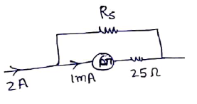
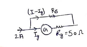
![]()
![]() m/s
m/s
Now,
![]()
![]()
![]()
Solution 9
![]()
![]()
![]()
Solution 10
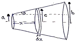
Resistance of the small strip
![]() -(i)
-(i)
Now,
![]()
![]()
Differentiate with respect to x
![]()
![]()
Now,
![]()
![]()
![]()
Solution 11
(a) ![]()
![]()
![]()
![]()
![]()
![]()
(b) ![]()
![]()
![]()
Solution 12
![]()
![]()
![]()
![]()
![]()
Solution 13
![]()
![]()
Solution 14
Resistance at temperature T is
given by ![]()
Let, at temperature T
![]()
![]()
![]()
![]()
![]()
![]()
Solution 15
Voltmeter reading=zero error + potential due to current
14.4=V+(1.75)R (i)
22.4=V+(2.75)R (ii)
Subtract (ii) from (i)
8=R
Put value in (i)
14.4=V+(1.75)8
V=0.4 volt
Solution 16
Initially, no current flows in circuit when switch is open.
So, emf of cell=voltmeter reading
ε=1.52V
Now, when switch is closed, cell is discharging
So, TPD=ε-ir
1.45=1.52-(1)(r)
r=0.07Ω
Solution 17
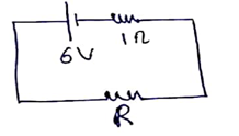
For battery
TPD=ε-ir
5.8=6-i(1)
i=0.2A
for external resistor
V=IR
5.8=(0.2)(R)
R=29Ω
Electric Current in Conductors Exercise 199
Solution 18
TPD=ε+ir
7.2=6+(2)(r)
r=0.6Ω
Solution 19
(a) Net emf across battery=9-6=3V,
Req=10Ω
current=3/10=0.3A
(b) Net emf across battery =9-6=3V
Resistance = 1Ω
Current=3/1=3A
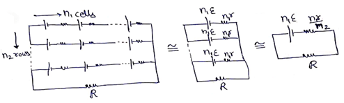
Solution 20
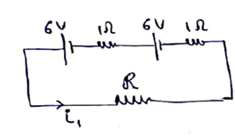
Cells are in series combination
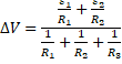
![]()
![]()
So, ![]()
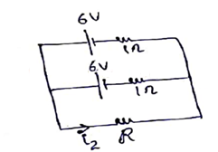
cells are in parallel combination
![]()
![]()
![]()
Divide (i) and (ii)
![]()
(a) ![]()
![]()
(b) ![]()
![]()
(c) ![]()
![]()
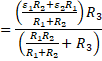
Solution 21
![]()
![]()
![]()
![]()
For I to be maximum,![]() will be minimum
will be minimum
To minimize,
![]()
![]()
Differentiate wrt![]()
![]()
![]()
![]()
![]()
Solution 22
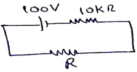
Emf=100V
Req= 10000+R
Current ![]()
For R=1Ω
![]()
For R=100Ω
![]()
So up to R=100Ω the current does not change up to 2 significant figures.
Solution 23
Voltage drop access A1=voltage drop access A2
I1R1=I2R2
(2.4)(20)=I2(30)
I2=1.6A
Reading in A3=reading in A1+reading in A2
=(2.4)+(1.6)
=4A
Solution 24
Emf=5.5V
![]()
![]()
for minimum current![]()
![]()
Now, for maximum current ![]()
![]()
Solution 25
For each bulb
Voltage applied=60V
Resistance=180Ω
Current I=![]()
(a) All bulbs switched on
IN=I1+I2+I3
IN=![]()
(b) Two bulbs switched on
IN=I1+I2
=![]()
=0.67A
(c) Only one bulb switched on
IN=![]() =0.33A
=0.33A
Solution 26
For maximum resistance all will be in series combination
Req=20+50+100=170Ω
For minimum resistance all will be in parallel combination
![]()
![]()
Solution 27
![]()
![]()
![]()
![]()
When bulbs are used in parallel, the equivalent resistance will be less than their individual resistance
∴ two resistances are 45Ω and 22.5Ω
Solution 28
Let I be the current in 20kΩ
So(12-I) will be current in 10kΩ
Now, V20kΩ=V10kΩ(parallel combination)
I(20)=(12-I)(10)
I=4mA
So,
I20kΩ=4mA
I10kΩ=8mA
I100kΩ=12mA
Equivalent resistance between AB
![]()
VAB=I![]()
=(12×10-3)(111.67×10³)
VAB=1340V
Solution 29
Initially,
V=IR
V=5R -(i)
Now, when 10Ω is connected in parallel to R
V=IReq
![]()
From (i) and (ii)
![]()
R=2Ω
Solution 30
![]()
![]()
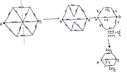
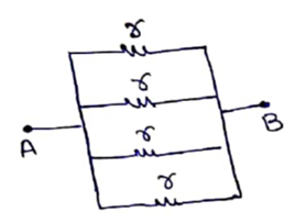
Solution 31
Resistance of each side of hexagon=15/6=2.5Ω
(a)
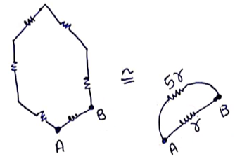
RAB=![]()
(b)
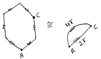
RAC=![]()
(c)
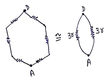
RAD=![]()
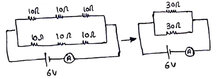
Solution 32
(a) Req=10+20=30Ω
V=3 volt
V=IR
3=I(30)
I=0.1A
(b) Req=10Ω
V=IR
3=I(10)
I=0.3A
Electric Current in Conductors Exercise 200
Solution 33
Emfeq=4-2=2V
Req=4+6=10Ω
Current![]()
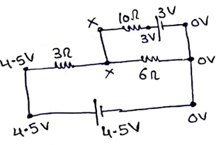
Solution 34
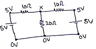
Potential at X
![]()
![]()
![]()
![]()
![]()
Solution 35
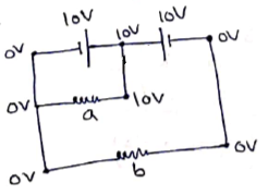
(a) For resistor a,
![]()
![]()
For resistor b,
![]()
![]()
(b)
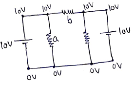
For resistor a,
![]()
![]()
For resistor b,
![]()
![]()
![]()
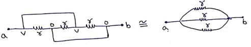
Solution 36
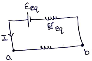
(a) Both cells are in parallel combination
![]()
Internal resistance of cell will be
![]()
Equivalent Resistance of circuit
![]()
So, current
![]()
Voltage difference across ab
![]()
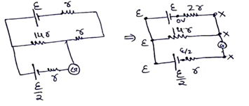
(b) The circuit can be redrawn as shown in figure
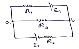
It is similar to above circuit in (a).
Hence same answer.
Solution 37
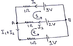
KVL for loop 1
3-I1(1)+I2(1)-2=0
I1-I2=1 -(i)
KVL for loop 2
2-I2(1)-( I1+I2)(1)-1=0
I1-2I2=1 -(ii)
Solving (i) and (ii)
I1=1A and I2=0A
Now,
VAB=TPD for cell of 2V
= ε-ir
= 2-(0)(1)
VAB = 2V
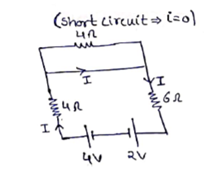
Solution 39
Potential difference across each resistance is 0
So, current =0
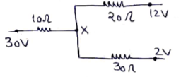
Solution 38
Potential at point of X volt
![]()
Solving, X=3V
Current in 10Ω resistance=![]()
Solution 40
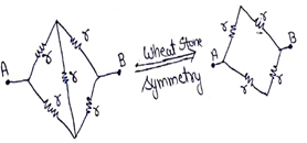
The circuit is in wheat stone symmetry
So, for all values of R, current=0.
Solution 41
(a)
![]()
![]()
(b)
![]()
![]()
Solution 42
The 50R resistors are in wheat stone symmetry, so no current flows in them
![]()
![]()
![]()
Electric Current in Conductors Exercise 201
Solution 43
(a) (Emf)eq = 12+6 = 18V
Req = 10+5 = 15Ω
Current I = ![]()
(b) Now,![]()
(c) ![]()
(d) Circuit in figure (b) is same as in figure (a)
Solution 44
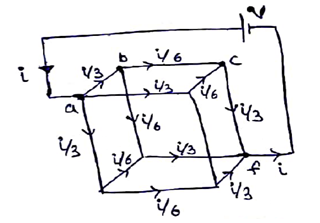
Apply KVL for abcfa
![]()
![]()
![]()
Solution 45
(a)

![]()
(b)
![]()
(c)
![]()
(d)
![]()
(e)
![]()
Solution 46
(a)
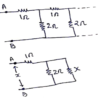
Let equivalent resistance between AB be x
![]()
![]()
![]()
(b)
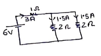
I=V/R=6/2=3A
Current in 2Ω
I2Ω=3/2=1.5A
Solution 47
(a)
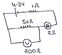
![]()
Current, ![]() (Ammeter reading)
(Ammeter reading)
Now,50Ω and 200Ω are in parallel combination
So, current is divided in inverse Ratio
current in voltmeter=![]()
= ![]() =0.02A
=0.02A
Voltmeter reading =(0.02)(200)=4V
(b)
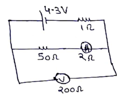
![]()
Current, ![]() (Ammeter reading)
(Ammeter reading)
TPD across cell=voltmeter reading
Voltmeter reading= ε-Ir=4.3-0.08(1)=4.2V
Solution 48
(a) ![]()
![]()
Since, 100Ω and 400Ω are in parallel combinationso, current is divided in inverse Ratio of resistances.
current in voltmeter Iv=![]()
Voltmeter reading ![]()
=![]()
![]() =24V
=24V
(b)
![]()
![]()
So,
V100Ω=IR=![]()
Solution 49
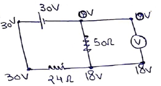
I24Ω=![]()
I50Ω=![]()
I24Ω= I50Ω+Iv [by KCL]
0.5=0.36+Iv
Iv=0.14A
For voltmeter,
Vv=IvRv
18=0.14R
Rv≃130Ω
Solution 50
Req=25+575=600Ω;I=10mA
V=IR
V=![]()
V=6 volt
Solution 51
IgRg=(I-Ig)Rs
(10-3)(25)=(2-10-3)Rs
Rs=1.25×10⁻²R
Solution 52
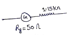
V=Ig(Rg+R)
12=Ig(50+1150)
Ig=0.01A
Now, IgRg=(I-Ig)Rs
(0.01)(50)=(2-0.01)Rs
Rs=0.25R
Solution 53
At null deflection, it will be in wheat-stone symmetry.
Let l be the balancing length from end A
![]()
Electric Current in Conductors Exercise 202
Solution 54
![]()
![]()
Solution 55
(a)
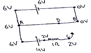
VA=6V
VC=2V
(b) Potential across AD=Potential across AC=4V
⇒ Potential across DB=2V
![]()
![]()
![]()
(c) No current will flow as VC=VD
(d) Potential difference across AC=potential at A-potential at C
7.5=6-Vc
VC=-1.5V
No points exist on wire AB as potential difference. Wire isalways greater than or equal to zero.
Solution 56
(a) Reqfor primary circuit=r+15r=16r
Current=![]()
VAB=IR
VAB=![]()
Potential gradient ![]()
Let balancing length be l from end A.
Emf=xl
![]()
![]()
(b)
Resistance of 560cm wire = ![]()
Resistance of 40cm wire=15r-14r=r
Nodal analysis at X
![]()
![]()
Potential difference across resistance r
![]()
![]()
![]()
Solution 57
In steady state, no current flows through capacitor
Req=10+20=30Ω
V=IR
2=I(30)
I=![]()
Voltage across capacitor=voltage across 10Ω
=IR
=![]()
=![]()
Q=CV
Q=6![]()
Solution 58
Nodal analysis at X
![]()
![]()
For 20Ω resistor
![]()
![]()
Solution 59
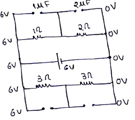
1Ω and 2Ω resistors are in series combination
![]()
![]()
So, potential across 1![]() =potential for 1Ω
=potential for 1Ω
=1×2=2volt
So, charge=CV=(1)(2)=2μC
Potential across 2μF=potential diff for 2Ω
=2×2=4V
So, charge=CV=(2)(4)=8μC
Now, for 3Ω-3Ω resistors,
Potential drop across each resistance is 3V
Charge on 3μF capacitor=CV
=(3μF)(3)=9μC
Charge on 4μF capacitor=CV
=(4μF)(3)=12μC
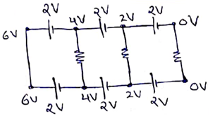
Solution 60
No current flows in steady state
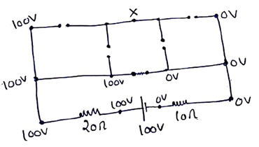
Nodal analysis at X
(X-100)3+(X-100)3+(X-0)1+(X-0)1=0
8X=600
X=75
VA-VB=100-75
=25V
VB-VC=75-0
=75V
Solution 61
(a) Maximum potential difference across resistor=ε
When charge on capacitor is 0
(b) At t=0, capacitor acts as short circuit
VR=ε=IR
![]()
(c) At t=∞, capacitor acts as open circuit
Vmax-cap.=ε
(d) ![]() (at t=∞,Vcap=ε)
(at t=∞,Vcap=ε)
(e) Power=εI
Pmax=εImax
Pmax=![]()
(f) Power dissipated=![]()
Solution 62
![]()
![]()
![]()
![]()
![]()
![]()
Solution 63
![]()
![]()
![]()
![]()
![]()
![]()
Solution 64
Q = Q0(1-![]() )
)
= (20![]()
= 12![]()
= 76μC
Solution 65
Q = Q0![]()
Q = 60 ![]()
Q = 6![]()
(a) t = 0
Q = 6![]()
(b) t = 30μs
Q = 6 ![]()
Q = 44μC
(c) t = 120μs
Q = (6 ![]()
= 18μC
(d) t = 1ms
Q = (6 ![]()
= 0.003μC
Solution 66
![]()
(a) ![]()
![]()
![]()
![]()
(b) ![]()
![]()
![]()
Electric Current in Conductors Exercise 203
Solution 67
Capacitance
![]()
![]()
Time constant
![]()
![]()
Electric field in capacitor =![]()
![]() )
)
![]()
![]()
Solution 68
Capacitance
![]()
![]()
charge
![]()
time constant =RC![]()
![]()
![]()
Energy stored=![]()
![]()
![]()
Solution 69
(a)
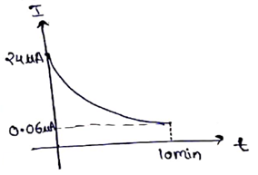
![]()
at t=0,
![]()
![]()
At t=10×60=600sec.
![]()
![]()
![]()
(b)
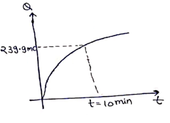
![]()
at ![]()
at ![]()
![]()
![]()
![]()
Solution 70
![]()
![]()
![]()
![]()
![]()
For discharging, ![]() so, answer will be same.
so, answer will be same.
Solution 71
![]()
![]()
![]()
![]()
![]()
Solution 72
![]()
![]()
![]()
![]()
![]()
![]()
![]()
Solution 73
Power=![]()
VI=![]()
I=![]()
![]()
![]()
![]()
Solution 74
Energy stored,![]()
![]()
Rate of energy stored=![]()
![]()
![]()
For maximum rate of energy stored
![]()
![]()
![]()
Put in (i)
![]()
![]()
Solution 75
(a) ![]()
(b) P=VI
=(6)(2.21)
P=13.25W
(c) Power dissipated=I2R
=(2.21)2(1)
=4.87W
(d) Energy stored ![]()
![]()
![]()
![]()
![]()
![]()
Solution 76
![]()
Heat dissipated ![]()
![]()

![]()
![]()
By energy method:-
Heat dissipated= energy stored at t=0-energy stored at time t
=![]()
![]()
Solution 77
Current in circuit at time t,
![]()
Heat dissipated
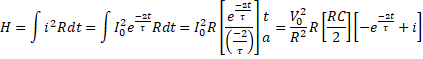
![]()
Solution 78
Capacitance
![]()
resistance of dielectric material,
![]()
time constant
![]()
![]()
It is independent of geometric parameters
Solution 79
![]()
![]()
![]()
![]()
![]()
![]()
So, charge on each capacitor=18.4/2=9.2μC
Solution 80
Initially, the capacitor was charged completely
Potential across capacitor=Potential across 10Ω
![]()
charge![]()
=![]()
![]()
Now, capacitor is discharged
![]()
![]()
![]()
![]()
Solution 81
During charging, charge developed in 4sec
![]()
![]()
![]()
![]()
Now discharging
![]()
![]()
![]()
Solution 82
Equivalent capacitance
![]()
![]()
![]()
Solution 83
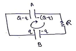
Let charge on capacitor B at time t be q
Applying KVL,
![]()
![]()
![]()
![]()
![]()
![]()
![]()
Solution 84
Initial charge given to the capacitor=Q
When the capacitor is connected by a battery, it will charge through the battery. The initial charge will also delay.
Growth of charge by battery
![]()
Delay of charge through capacitor
![]()
Net charge on capacitor at time ![]()