Class 10 SELINA Solutions Physics Chapter 3 - Machines
Machines Exercise Ex. 3A
Solution A.5
(a) M.A. = η × V.R.
As we know,
![]()
i.e., M.A = η × V.R
Solution A.8
(d) A machine can have a mechanical advantage greater than the velocity ratio.
Reason: If the mechanical advantage of a machine is greater than its velocity ratio, then it would mean that the efficiency of a machine is more than 100%, which is practically not possible.
Solution A.9
(c) Effort is between fulcrum and load
Hint: Levers, for which the mechanical advantage is less than 1, always have the effort arm shorter than the load arm.
Solution A.10
M. A. > 1
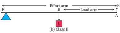
Hint: In class II levers, the load is in between the effort and fulcrum. Thus, the effort arm is always longer than the load arm and less effort is needed to overcome a large load. Hence, M.A. > 1.
Solution B.1
(a) A machine is a device by which we can either overcome a large resistive force at some point by applying a small force at a convenient point and in a desired direction or by which we can obtain a gain in the speed.
(b) An ideal machine is a machine whose parts are weightless and frictionless so that which there is no dissipation of energy in any manner. Its efficiency is 100%, i.e. the work output is equal to work input.
Solution B.2
(a)To multiply force: a jack is used to lift a car.
(b)To change the point of application of force: the wheel of a cycle is rotated with the help of a chain by applying the force on the pedal.
(c)To change the direction of force: a single fixed pulley is used to lift a bucket full of water from the well by applying the effort in the downward direction instead of applying it upwards when the bucket is lifted up without the use of pulley.
(d)To obtain gain in speed: when a pair of scissors is used to cut the cloth, its blades move longer on cloth while its handles move a little.
Solution B.3
For an ideal machine mechanical advantage is numerically equal to the velocity ratio.
Solution B.4
(i) For a machine working as a force multiplier, displacement of load is less than displacement of effort. Thus, the velocity ratio is more than 1.
(ii) For a machine working as a speed multiplier, displacement of load is more than displacement of effort. Thus, the velocity ratio is less than 1.
Solution B.5
The mechanical advantage for an actual machine is equal to the product of its efficiency and velocity ratio.
![]()
The efficiency of such a machine is always less than 1, i.e. h
Solution B.6
![]()
This is the expression of the mechanical advantage of a lever.
Solution B.7
(a) More than one: shears used for cutting the thin metal sheets.
(b)Less than one: a pair of scissors whose blades are longer than its handles.
Solution B.8
- Class II
- Class I
- Class I
- Class II
- Class III
- Class III
Solution B.9
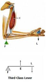
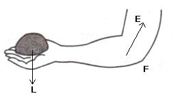
(a) Class III.
Here, the fulcrum is the elbow of the human arm. Biceps exert the effort in the middle and load on the palm is at the other end.
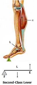
(b) Class II.
Here, the fulcrum is at toes at one end, the load (i.e. weight of the body) is in the middle and effort by muscles is at the other end.
Solution B.10
- Class I lever in the action of nodding of the head: In this action, the spine acts as the fulcrum, load is at its front part, while effort is at its rear part.
- Class II lever in raising the weight of the body on toes: The fulcrum is at toes at one end, the load is in the middle and effort by muscles is at the other end.
- Class III lever in raising a load by forearm: The elbow joint acts as fulcrum at one end, biceps exerts the effort in the middle and a load on the palm is at the other end.
Solution B.11
(a) Mechanical advantage = efficiency × velocity ratio
(b) In class II lever, effort arm is greater than the load arm.
(c) A scissors is a speed multiplier.
Solution C.1
Machines are useful to us in the following ways:
(1)In lifting a heavy load by applying a less effort.
(2)In changing the point of application of effort to a convenient point.
(3)In changing the direction of effort to a convenient direction.
(4)For obtaining a gain in speed.
Solution C.2
The purpose of jack is to make the effort less than the load so that it works as a force multiplier.
Solution C.3
An ideal machine is a machine whose parts are weightless and frictionless so that which there is no dissipation of energy in any manner. Its efficiency is 100%, i.e. the work output is equal to work input.
|
Ideal machine
|
Practical machine
|
|
1. Efficiency is 100%.
|
1. Efficiency is less than 100%
|
|
2. Its parts are weightless, elastic and perfectly smooth.
|
2. Its parts are not weightless, elastic or perfectly smooth.
|
|
3. There is no loss in energy due to friction.
|
3. There is always some loss of energy due to friction.
|
|
4. Work output of such a machine is equal to the work input.
|
4. Work output is always less than the work input.
|
Solution C.4
The ratio of the load to the effort is called mechanical advantage of the machine. It has no unit.
Solution C.5
The ratio of the velocity of effort to the velocity of the load is called the velocity ratio of machine. It has no unit.
Solution C.6
It is the ratio of the useful work done by the machine to the work put into the machine by the effort.
In actual machine there is always some loss of energy due to friction and weight of moving parts, thus the output energy is always less than the input energy.
Solution C.7
(a) A machine acts as a force multiplier when the effort arm is longer than the load arm. The mechanical advantage of such machines is greater than 1.
(b) A machine acts a speed multiplier when the effort arm is shorter than the load arm. The mechanical advantage of such machines is less than 1.
It is not possible for a machine to act as a force multiplier and speed multiplier simultaneously. This is because machines which are force multipliers cannot gain in speed and vice-versa.
Solution C.8
Mechanical advantage is equal to the product of velocity ratio and efficiency.
![]()
For a machine of a given design, the velocity ratio does not change.
Solution C.9
This is because the output work is always less than the input work, so the efficiency is always less than 1 because of energy loss due to friction.
![]()
Solution C.10
A lever is a rigid, straight or bent bar which is capable of turning about a fixed axis.
Principle: A lever works on the principle of moments. For an ideal lever, it is assumed that the lever is weightless and frictionless. In the equilibrium position of the lever, by the principle of moments,
Moment of load about the fulcrum=Moment of the effort about the fulcrum.
Solution C.11
The three classes of levers are:
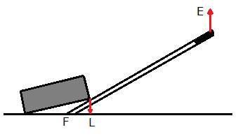
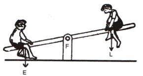
(i)Class I levers: In these types of levers, the fulcrum F is in between the effort E and the load L. Example: a seesaw, a pair of scissors, crowbar.
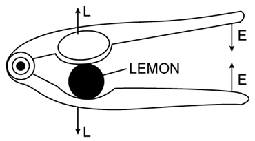
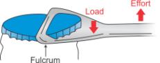
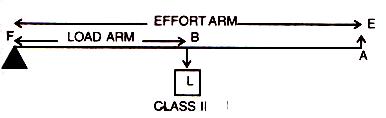
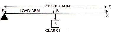
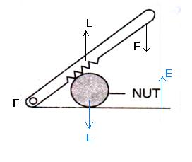
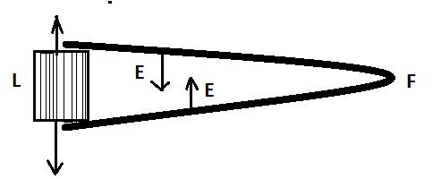
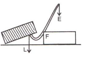
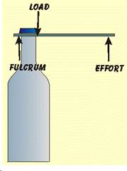
(ii)Class II levers: In these types of levers, the load L is in between the effort E and the fulcrum F. The effort arm is thus always longer than the load arm. Example: a nut cracker, a bottle opener.
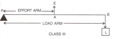
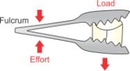
(iii)Class III levers: In these types of levers, the effort E is in between the fulcrum F and the load L and the effort arm is always smaller than the load arm. Example: sugar tongs, forearm used for lifting a load.
Solution C.12
A pair of scissors and a pair of pliers both belong to class I lever.
A pair of scissors has mechanical advantage less than 1.
Solution C.13
(a)
(b) It is class II lever.
Solution C.14
a)
b) This rod is a class II lever as load is between fulcrum and effort.
c) An example of class II lever is a bottle opener.
Solution C.15
Classes III levers always have mechanical advantage less than one.
Diagram:
Solution C.16
In these types of levers, the effort is in between the fulcrum F and the load L and so the effort arm is always smaller than the load arm. Therefore M.A. < 1.
Solution C.17
With levers of class III, we do not get gain in force, but we get gain in speed, that is a longer displacement of load is obtained by a smaller displacement of effort.
Solution C.18
(a) A bottle opener is a lever of the second order, as the load is in the middle, fulcrum at one end and effort at the other.
Bottle opener
(b) Sugar tongs is a lever of the third order as the effort is in the middle, load at one end and fulcrum at the other end.
Sugar tongs
Solution C.19
It is Class III lever.
Solution D.1
Let a machine overcome a load L by the application of an effort E. In time t, let the displacement of effort be dE and the displacement of load be dL.
Work input = Effort X displacement of effort
= E X dE
Work output = Load X displacement of load
= L X dL
Efficiency ![]()

![]()
![]()
![]()
![]()
Thus, mechanical advantage of a machine is equal to the product of its efficiency and velocity ratio.
Solution D.2
A pair of scissors used to cut a piece of cloth has blades longer than the handles so that the blades move longer on the cloth than the movement at the handles.
While shears used for cutting metals have short blades and long handles because as it enables us to overcome large resistive force by a small effort.
Solution D.3
(a) The weight W of the scale is greater than E.
It is because arm on the side of effort E is 30 cm and on the side of weight of scale is 10 cm. So, to balance the scale, weight W of scale should be more than effort E.
(b)

Solution D.4
Class II lever always have a mechanical advantage more than one.
Example: a nut cracker.
To increase its mechanical advantage we can increase the length of effort arm.
Solution D.5
Diagram:
The effort arm is longer than load arm in such a lever.
Solution D.6
In these types of levers, the load L is in between the effort E and the fulcrum F. So, the effort arm is thus always longer than the load arm. Therefore M.A>1.
Solution D.7
Diagram:
Example: a bottle opener.
Solution D.8
When the mechanical advantage is less than 1, the levers are used to obtain gain in speed. This implies that the displacement of load is more as compared to the displacement of effort.
Solution D.9
Diagram:

Examples: foot treadle.
Solution D.10
(a)A seesaw
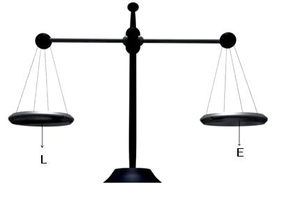
(b)A common balance
(c)A nut cracker
(d)Forceps.
Solution E.1
Total length of crowbar =120 cm
Load arm =20 cm
Effort arm = 120-20 =100 cm
Mechanical advantage ![]()
![]()
Solution E.2
Effort arm = 7.5 cm
Load arm = 15 cm
Mechanical advantage![]()
Solution E.3
Effort arm = 10 cm
Load arm = 5 cm
Mechanical advantage=![]()
Load=5kgf
![]()
Solution E.4
(a)This is a class I lever.
(b)Given AB=1m, AF=0.4m and BF=0.6 m
Mechanical advantage![]()
(c)Load =15kgf
![]()
Solution E.5
Diagram:
Crowbar is a class I lever.
(i)Total length of crowbar =1.5m
Effort arm = 1 m
Load arm = 1.5-1 =0.5 m
(ii)Effort arm= 1m
(iii)Mechanical advantage![]()
(iv)The effort needed
![]()
Solution E.6
Effort arm = 2 cm
Load arm = 8.0 cm
Given effort =10kgf
(i)Mechanical advantage ![]()
(ii)![]()
The pair of scissors acts as a speed multiplier because MA < 1.
Solution E.7
Total length of rod = 4 m = 400 cm
(a)18kgf load is placed at 60 cm from the support.
W kgf weight is placed at 250 cm from the support.
By the principle of moments
18 x 60 = W x 250
W = 4.32 kgf
(b)Given W=5 kgf
18kgf load is placed at 60 cm from the support.
Let 5 kgf of weight is placed at d cm from the support.
By the principle of moments
18 x 60 = 5 x d
d = 216 cm = 2.16 m from the support on the longer arm.
(c)It belongs to class I lever.
Solution E.8
(a) Length of the lever is same as the effort arm. Also, effort arm is more than load arm. So, this is a class II lever.
(b)
(c) Mechanical advantage is

Relation between MA, efficiency and V.R. is
![]()
(d) When efficiency reduces, its mechanical advantage reduces and velocity ratio remains the same. So, when efficiency becomes 50%, M.A. = 0.9 and V.R. = 1.8
Solution E.9
It belongs to second class lever.
The mechanical advantage of the lever will increase when load is shifted towards the fulcrum.
Solution E.10
(a) (i) Load arm AF=20 cm
(ii)Effort arm CF=60 cm
(iii)Mechanical advantage ![]()
(iv)Total load =30+15 = 45 kgf
![]()
Solution E.11
(a)The principle of moments: Moment of the load about the fulcrum=moment of the effort about the fulcrum
FB x Load = FA x Effort
(b)Class III;Sugar tongs the example of this class of lever.
(c)Given: FA=10 cm, AB = 500 cm, BF =490+10=500 cm.
The mechanical advantage
![]()
The minimum effort required to lift the load
Solution E.12
Fire tongs has its arms =20 cm
Effort arm = 15 cm
Load arm =20 cm
(i)Mechanical advantage ![]()
(ii)![]() .
.
Solution A.1
(b) A single fixed pulley used to lift a bucket of water from a well.
A jack, bar, and wheelbarrow all increase the mechanical advantage, allowing you to lift a heavier object with less force. A single fixed pulley simply changes the direction of the force, not the amount.
Solution A.2
(a) Output energy = Input energy
An ideal machine means the machine has 100% efficiency, which means all the input energy is converted to output energy.
Solution A.3
(b) Due to friction, mechanical advantage of a machine increases.
Friction opposes the motion and consumes more energy. Thus, due to the friction, mechanical advantage reduces.
Solution A.4
(d) No unit
Velocity ratio is defined as the ratio of distance moved by effort to distance moved by load. Since it's a ratio of similar quantities, it becomes dimensionless and has no unit.
Solution A.6
(c) Efficiency = Work input / Work output
The correct efficiency formula is,
Efficiency = Work output/ Work input
Solution A.7
(a) Greater than 1
If the effort needed is less than the load, then mechanical advantage of the machine is greater than 1.
Mechanical advantage is the ratio of the output force (load) to the input force (effort). If the effort required is less than the load, it means the machine is amplifying the force. Thus, a ratio greater than 1 indicates that the output is greater than the input.
Solution A.11
(a) Class I lever
In Class I lever, fulcrum lies between effort and load.
Solution A.12
(d) Class II or Class III lever
Fulcrum lies between load and effort only in the Class I lever. In class II and class III levers, effort and load are on the same side of the fulcrum.
Solution A.13
(b) Class II lever
In a class II lever, the load (bottle cap) is positioned between the fulcrum (hinge point of the opener) and the effort (your hand applying force on the handle). This arrangement allows you to apply a smaller force (effort) with a larger handle to overcome the resistance of the bottle cap (load).
Machines Exercise Ex. 3B
Solution A.2
(d) helps in applying effort in a convenient direction.
Explanation: A single fixed pulley though does not reduce the effort but helps in changing the direction of effort applied. As it is far easier to apply effort in downward direction, the single fixed pulley is widely used.
Solution A.4
(b) 2
The mechanical advantage of an ideal single movable pulley is 2.
Derivation: Consider the diagram given below:
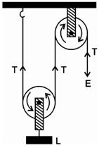
Here the load L is balance by the tension in two segments of the string and the effort E balances the tension T at the free end, so
L = T + T = 2T and E = T
Assumption: Weight of the pulley is negligible.
We know that,
![]()
Thus, a single movable pulley has a M.A. equal to 2.
Solution B.1
The ideal mechanical advantage of a single fixed pulley is 1.
It cannot be used as force multiplier.
Solution B.2
The velocity ratio of a single fixed pulley is 1.
Solution B.3
The load rises upwards with the same distance x.
Solution B.4
(a)Multiply force: a movable pulley.
(b)Multiply speed: gear system or class III lever.
(c)Change the direction of force applied: single fixed pulley.
Solution B.5
- The velocity ratio of a single fixed pulley is always more than 1.(false)
- The velocity ratio of a single movable pulley is always 2.(true)
- The velocity ratio of a combination of n movable pulleys with a fixed pulley is always 2n.(true)
- The velocity ratio of a block and tackle system is always equal to the number of strands of the tackle supporting the load. (true)
Solution C.1
Fixed pulley: A pulley which has its axis of rotation fixed in position, is called a fixed pulley.
Single fixed pulley is used in lifting a small load like water bucket from the well.
Solution C.2
There is no gain in mechanical advantage in the case of a single fixed pulley. A single fixed pulley is used only to change the direction of the force applied that is with its use, the effort can be applied in a more convenient direction. To raise a load directly upwards is difficult.
Solution C.3
Single movable pulley: A pulley, whose axis of rotation is not fixed in position, is called a single movable pulley.
Mechanical advantage in the ideal case is 2.
Solution C.4
The efficiency of a single movable pulley system is not 100% this is because
(i)The friction of the pulley bearing is not zero ,
(ii)The weight of the pulley and string is not zero.
Solution C.5
The velocity ratio of a single movable pulley is always 2. The friction in the pulley bearing has no effect on it.
Solution C.6
The load is raised to a height of x/2.
Solution C.7
(a) In a single fixed pulley, some effort is wasted in overcoming friction between the strings and the grooves of the pulley; so the effort needed is greater than the load and hence the mechanical advantage is less than the velocity ratio.
(b) This is because of some effort is wasted in overcoming the friction between the strings and the grooves of the pulley.
(c) This is because mechanical advantage is equal to the total number of pulleys in both the blocks.
(d) The efficiency depends upon the mass of lower block; therefore efficiency is reduced due to the weight of the lower block of pulleys.
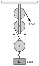
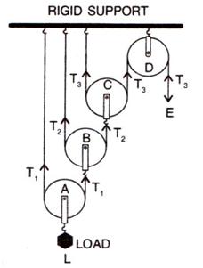
Solution D.1
A single movable pulley act as a force multiplier.
Diagram:
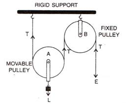
Solution D.2
The force should be in upward direction.
The direction of force applied can be changed without altering its mechanical advantage by using a single movable pulley along with a single fixed pulley to change the direction of applied force.
Diagram:
Solution D.3
Diagram:
Ideal mechanical advantage of this system is 2. This can be achieved by assuming that string and the pulley are massless and there is no friction in the pulley bearings or at the axle or between the string and surface of the rim of the pulley.
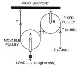
Solution D.4
(a)

(b) The fixed pulley B is used to change the direction of effort to be applied from upward to downward.
(c) The effort E balances the tension T at the free end, so E=T
(d) The velocity ratio of this arrangement is 2.
(e) The mechanical advantage is 2 for this system (if efficiency is 100%).
(f) If the efficiency of the system is 100%, then effort applied is equal to half the load. Hence, it acts as a force multiplier and the mechanical advantage is 2.
Solution D.5
|
Single fixed pulley |
Single movable pulley
|
|
1.It is fixed to a rigid support. |
1.It is not fixed to a rigid support. |
|
2.Its mechanical advantage is one. |
2.Its mechanical advantage istwo. |
|
3.Its velocity ratio is one. |
3.Its velocity ratio is two. |
|
4.The weight of pulley itself does not affect its mechanical advantage. |
4. The weight of pulley itself reduces its mechanical advantage. |
|
5.It is used to change the direction of effort |
5.It is used as force multiplier. |
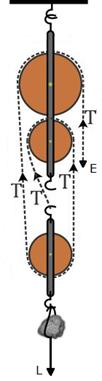
Solution D.6
(a) Pulleys A and B are movable pulleys. Pulley C is fixed pulley.
(b)
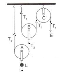
(c) The magnitude of effort E = T1
And the magnitude of L= 22 T1 = 4 T1
(d)The mechanical advantage = 22 = 4
The velocity ratio = 22 = 4
(e)Assumption: the pulleys A and B are weightless.
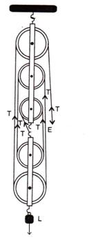
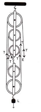
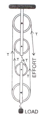
Solution D.7
Diagram:
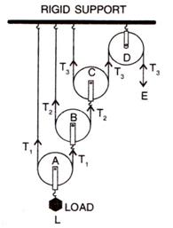
Tension T1 in the string passing over the pulley A is given as
2T1 = L or T1 = L/2
Tension T2 in the string passing over the pulley B is given as
2T2 = T1or T2 = T1/2 = L/22
Tension T3 in the string passing over the pulley C is given as
2T3 = T2orT3 = T2/2 = L/23
In equilibrium, T3 = E
E =L/23
Mechanical advantage = MA = L/E = 23
As one end of each string passing over a movable pulley is fixed, so the free end of string moves twice the distance moved by the movable pulley.
If load L moves up by a distance x, dL = x, effort moves by a distance 23x, dE = 23x
Velocity Ratio VR =![]()
Efficiency = MA/VR =23/ 23 = 1 or 100%
Solution D.8
Solution E.1
The force applied by the women is= 70 N
The mass of bucket and water together is = 6 kg
Total load = 6 x 10 = 60 N
Mechanical advantage ![]()
Solution E.2
(a) Effort driving the pulley is, E = mg = 100 × 10 = 1000 N
Input power is

(b) Load pulled by the pulley is L = 75 × 10 = 750 N
Therefore, M.A. is
![]()
When the effort moves by a distance d downwards, the load moves by the same distance upwards. So, V.R. = 1
Hence, efficiency is
![]()
(c) When the effort moves by a distance d downwards, the load moves by the same distance upwards. So, height to which the load moves is 8 m.
Solution E.3
In case of a single fixed pulley, the effort (Ef needed to lift a load) is equal to the load itself.
Thus, Ef = L
→ Ef = 50 kgf
In case of a single movable pulley, the effort needed to lift a load is equal to half the load.
→ Em =![]()
→ ![]()
Thus, the ratio of efforts applied by the respective pulley is
![]()
Ef:Em = 2:1
Solution E.4
Load = 75 kgf
Effort=25kgf
n = 3
MA = Load/Effort = 75/25 = 3
or MA = n = 3
velocityratio VR= n = 3
Efficiency ![]() or 100%
or 100%
Solution E.5
A block and tackle system has 5 pulleys. (n = 5)
Effort=1000 N
Load=4500 N
(a)The mechanical advantage ![]()
(b)The velocity ratio = n =5
(c)The efficiency of the system![]()
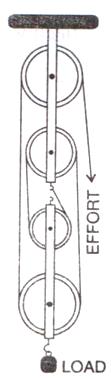
Solution E.6
(a)
(b)The effort move = 1 x 5 = 5m
(c)Five strands of tackle are supporting the load.
(d)Mechanical advantage of the system =![]()
Solution E.7
Load= 150N
Effort=60N
Mechanical advantage=L/E=150/60=2.5
The pulley system is not ideal because the mechanical advantage is less than 3.
Solution E.8
(a)
(b)Velocity ratio of the system = n = 4
(c)The relation between load and effort
MA = ![]()
![]()
(d)(i) There is no friction in the pulley bearings, (ii) weight of lower pulleys is negligible and (iii) the effort is applied downwards.
Solution E.9
(a)There are 4 strands of tackle supporting the load.
(b)
(c)The mechanical advantage of the system
![]()
(d) When load is pulled up by a distance 1 m, the effort end will move by a distance = 1x4 = 4m.
(e) MA = Load/Effort
100 = 4 x E
E = 100/4 = 25 N
(f) The V.R. of the block and tackle system will remain the same even if the weight of the movable block is doubled, as long as the number of strands supporting the load remains the same.
∴ V.R = 4
Solution E.10
For block and tackle system, V.R. = n (number of pulleys)
Hence, n = 3
The diagram is as shown below
(a) The effort put by man is E = 200 kgf
Efficiency is η = 60%
For block and tackle system,

Hence, load is
![]()
(b) The velocity ratio of system is V.R. = 3
Hence, we get

Solution E.11
Assumptions: (i) There is no friction in the pulley bearing, (ii) the pulleys and the string are massless.
Solution A.1
(b) as a force multiplier
Pulley systems do not gain energy, it just changes the direction and magnitude of the applied force.
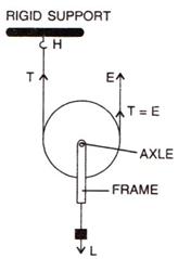
Solution A.3
(b) 1
A fixed pulley, as shown in the figure, does not change the force required to lift the load. It simply changes the direction of the applied force.
Therefore, the velocity ratio (ratio of the distance moved by the effort to the distance moved by the load) is 1. The boy lifts the load 5 meters, and the rope also moves 5 meters through the pulley.
Solution A.5
All the statements given are correct.
Note: None of the options for this question is correct.
Solution A.6
(a) 2n
If there are n movable pulleys with one fixed pulley, the mechanical advantage is given by 2n.
Solution A.7
(d) (3) and (4)
The statements related to velocity ratio and mechanical advantage for the pulley system are incorrect. The ideal velocity ratio for both the system is 1 and mechanical advantage for movable pulley system is greater than 1.
Solution A.8
(c) M.A. < V.R.
The relationship between mechanical advantage (M.A.) and velocity ratio (V.R.) for a practical machine is,
M.A. < V.R.
Solution A.9
(b) 2: 1
In a movable pulley system, the pulley is attached to the load, and the effort force is applied downward. The load is also lifted upward, but because the pulley is attached to the load, the load's weight is distributed between the two sections of the rope, effectively halving the load seen by the effort.
Let's denote the effort force required to lift the load using a fixed pulley as Ef and the effort force required to lift the load using a movable pulley as Em
Ef = 50 kgf
Em = 50/2 = 25kgf
Thus, the ratio of two efforts will be,
Ef/Em = 2/1
Thus, the ratio of the two effort is 2:1.
Solution A.10
(b) 5
In a block and tackle system of 5 pulleys, 5 strands will be supporting the load.
Solution A.11
(b) 4
In a block and tackle system of 4 pulleys, 4 strands will be supporting the load.
Solution A.12
(a) n = 1 – W/nE
For a system of n pulleys, the weight of the lower block along with pulleys is W, then its efficiency is given by:
η= 1- W/nE