CBSE Class 12-science Answered
Draw the circuit diagram of a common-emitter amplifier using an n-p-n transistor. What is the phase difference between the input signal and output voltage ? Draw the input and output wave forms of the signal. Write the expression for its voltage gain. State two reasons why a common emitter amplifier is preferred to a common base amplifier
Asked by Topperlearning User | 01 Jul, 2014, 11:21: AM
The circuit of a common-emitter amplifier using an n-p-n transistor is shown below :
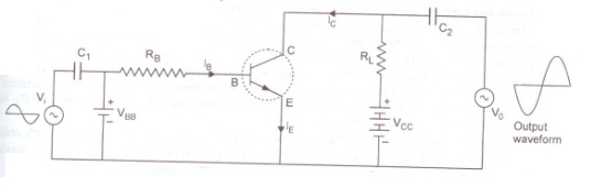
In a common emitter amplifier circuit, the input signal voltage and output collector voltage are in opposite phase. i.e 180° out of phase. Thus the phase difference between the input signal and output voltage is 180°.
The input and output wave forms are shown in fig.

where β is the current gain , RL the load resistance and Ri the input resistance.
Reasons for using a common emitter amplifier over common base amplifier:
(i) Voltage gain is quite high without any phase change of signal voltage.
(ii) Voltage gain is uniform over a wide frequency range or power gain is high .
Answered by | 01 Jul, 2014, 01:21: PM
Concept Videos
-
Applications of Transistors - Part 1
 This video explains amplification with the help of a transistor.
 -
Applications of Transistors - Part 2 ...
 This video gives details of terms related to transistor and also the use of...
 -
Applications of transistors
 Applications of transistors
CBSE 12-science - Physics
Asked by Www.harshalhire51 | 20 Nov, 2019, 09:48: PM
CBSE 12-science - Physics
Asked by Topperlearning User | 10 Jul, 2014, 02:24: PM
CBSE 12-science - Physics
Asked by Topperlearning User | 24 Jun, 2014, 02:36: PM
CBSE 12-science - Physics
Asked by Topperlearning User | 01 Jul, 2014, 10:01: AM
CBSE 12-science - Physics
 The adjoining figure shows a common emitter transistor amplifier which uses a silicon transistor. If the quiescent emitter current is 1 mA what is the base biasing voltage?
Asked by Topperlearning User | 10 Jul, 2014, 02:32: PM
CBSE 12-science - Physics

Asked by Topperlearning User | 10 Jul, 2014, 02:06: PM
CBSE 12-science - Physics
Asked by Topperlearning User | 10 Jul, 2014, 01:52: PM
CBSE 12-science - Physics
Asked by Topperlearning User | 10 Jul, 2014, 03:03: PM
CBSE 12-science - Physics
Asked by Topperlearning User | 01 Jul, 2014, 10:48: AM
CBSE 12-science - Physics
Asked by Topperlearning User | 04 Jun, 2014, 01:23: PM