CBSE Class 12-science Answered
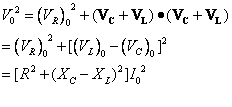
The diagram of AC generator:
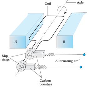
Basic parts of the AC generator:
i. Rectangular coil mounted on a rotor shaft. The coil also called armature is mechanically rotated in the uniform magnetic field by some external means.
ii. The axis of rotation of the coil is perpendicular to the direction of the magnetic field. The rotation of the coil causes the magnetic flux through it to change, so an emf is induced in the coil.
iii. The ends of the coil are connected to an external circuit by means of slip rings and brushes.
iv. N and S are two permanent magnets which provide a constant magnetic field region in which the coil rotates.
Principle of working:
A wire loop of area A is free to rotate
about an axis which is perpendicular to a uniform magnetic field B. If the
normal to the loop makes an angle ![]() with
with ![]() then, flux
through the loop
then, flux
through the loop ![]() .
.
If this loop rotates with a constant
angular velocity ![]()
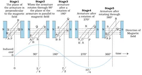
The flux through it changes at the rate,
![]()
where Co is a constant
![]() emf is induced between ends A and B given
by:
emf is induced between ends A and B given
by:
![]()
![]() , here
, here ![]() Peak value of
emf generated.
Peak value of
emf generated.
Since the emf induced in the coil is varying as a function of sine, it is alternating in value and direction
Or
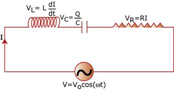
If I
is the instantaneous current through LCR circuit, the instantaneous voltage
across the resistor is![]() , across the inductor is
, across the inductor is ![]() and across the
capacitor is
and across the
capacitor is ![]() .
.
From conservation of energy, when all of them are connected in series, the total work required is just the sum of these.
So, ![]()
The current will have the same frequency as V, but in general will not be in phase with V.
The current can be written as
![]()
with the peak value![]() and the relative phase
and the relative phase![]() fixed by equation.
fixed by equation.
Hence the voltage equations across each of the components will be

where ![]() with
with ![]() .
.
In the phasor diagram, the external
source of EMF is ![]() (peak value),
which is the x component of the
phasor
(peak value),
which is the x component of the
phasor![]() , this vector will be along the X axis.
, this vector will be along the X axis.
The current phasor![]() will be at an angle
will be at an angle![]() relative to this.
relative to this.
So, since![]() , it will be parallel to this current phasor I, at
angle
, it will be parallel to this current phasor I, at
angle![]() relative to
relative to![]() .
.
![]() will make an angle
will make an angle![]() and
and![]() will make angle
will make angle![]() relative to
relative to![]() .
.
This also implies that![]() and
and![]() will lie in opposite
directions, as the following figure shows.
will lie in opposite
directions, as the following figure shows.
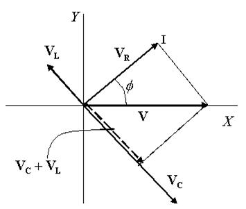
The vector![]() is
perpendicular to the vector
is
perpendicular to the vector![]() ,
and also, of course,
,
and also, of course, ![]()
Taking the dot product
![]() gives
gives
From this, we get
![]()
The factor Z is the analog of resistance in a purely resistive circuit, and is called Impedance.
The phase angle ![]() is found as
is found as
![]()
Condition for resonance:
The amplitude or peak value of the
current through the circuit will be 
The expression clearly shows that![]() is maximum if the term inside the bracket in the
denominator is zero, since then the
denominator is minimum and the
impedance is completely resistive.
is maximum if the term inside the bracket in the
denominator is zero, since then the
denominator is minimum and the
impedance is completely resistive.
This means that the current is maximum at
frequency![]() , such that
, such that ![]()
![]()
The maximum current is![]() , as if the reactive elements are not there at all!
, as if the reactive elements are not there at all!
This phenomenon, in which the peak value of current shoots up at this particular frequency is called 'resonance'.
The condition for resonance is hence:
![]()
Power factor:
Average power dissipated per cycle, is given by
![]()
The factor ![]() is called the 'Power Factor', since the power
crucially depends on it. This factor depends on the applied frequency, apart
from circuit parameters like L,C
and R.
is called the 'Power Factor', since the power
crucially depends on it. This factor depends on the applied frequency, apart
from circuit parameters like L,C
and R.
At resonance,![]() , so that
, so that![]() . This implies that
. This implies that![]() , or that the power factor attains its maximum value,
equal to unity.
, or that the power factor attains its maximum value,
equal to unity.
For the (ii) capacitive
and (iii) inductive circuits, the current and voltage differ in phase by![]() , so either way, it is minimum, ie., zero.
, so either way, it is minimum, ie., zero.
Concept Videos
-
AC Applied to a Series LCR in Circuit - Part 1
 This video explains finding the current in a series LCR circuit with an AC ...
 -
AC Applied to a Series LCR in Circuit - Part 2
 This video explains finding out the total impedence and phase constant for ...
 -
AC Applied to a Series LCR in Circuit - Exam Decoded ...
 This video contains practice questions and numerical problems on AC applied...